Tools Required
J 42640 Steering Column Anti-Rotation Pin
Removal Procedure
- Lock the steering column by installing J 42640 into the underside of the steering column.
- Disconnect the negative battery cable. Refer to Battery Negative Cable Disconnection and Connection in Engine Electrical.
- Remove the air cleaner assembly. Refer to Air Cleaner Assembly Replacement in Engine Controls - 3.8L.
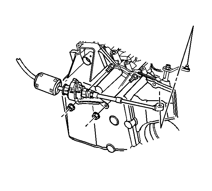
- Use a large flat-bladed tool in order to remove the range selector cable from the range selector lever.
- Remove the range selector cable with bracket from the transmission case and set aside.
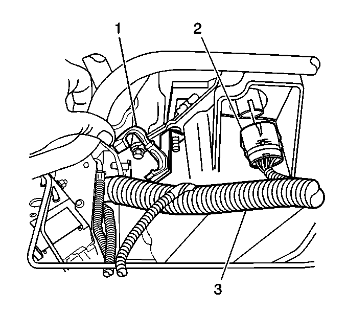
- Disconnect the transaxle electrical connector C100 (2).
- Remove the wiring harness (3) from the wiring harness retainer (1) on the transaxle.
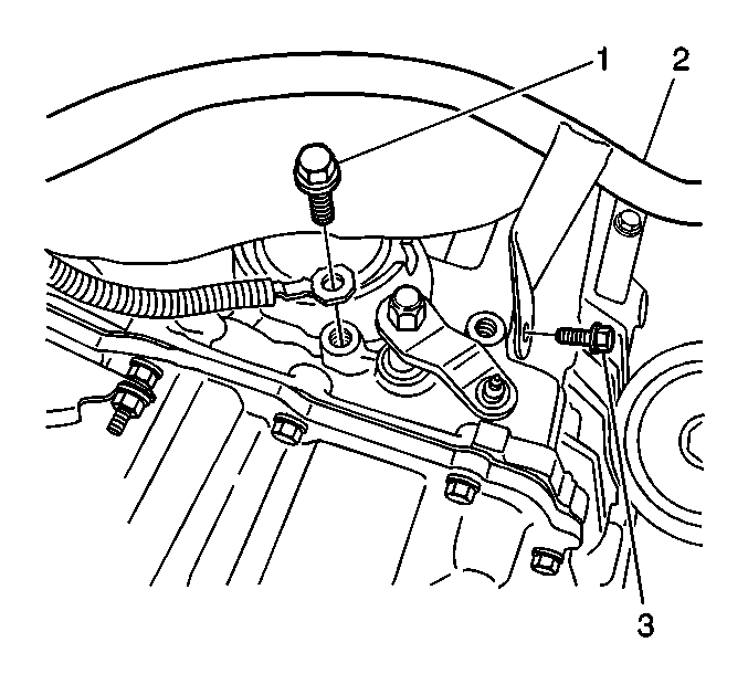
- Remove the ground cable bolt (1) from the transaxle.
- Install the engine support fixture. Refer to Engine Support Fixture in Engine Mechanical - 3.8L.
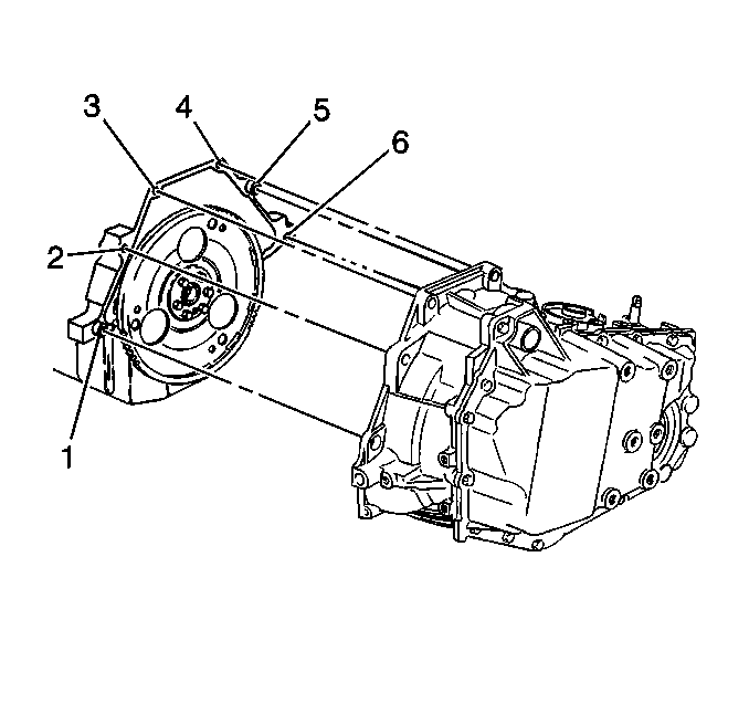
- Remove the upper engine to transaxle case bolts (2-5).
- Raise and Support the vehicle. Refer to Lifting and Jacking the Vehicle in General Information.
- Remove the front tire and wheel assembly. Refer to Tire and Wheel Removal and Installation in Tires and Wheels.
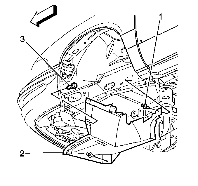
- Remove both of the inner wheelhouse fillers (2). Refer to Front Bumper Fascia Extension Replacement in Bumpers.
- Remove the front air deflector. Refer to Front Air Deflector Replacement in Body Front End.
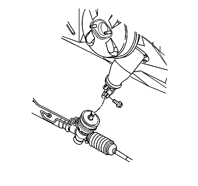
- Remove the intermediate shaft lower pinch bolt.
- Disconnect the intermediate shaft from the power steering gear.
- Remove the power steering gear heat shield. Refer to Steering Gear Heat Shield Replacement in Power Steering system.
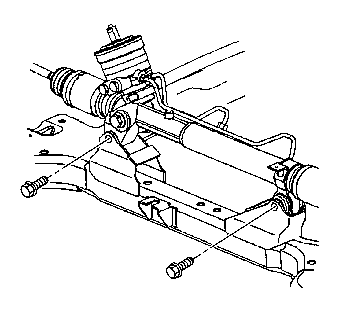
- Remove the power steering gear mounting bolts.
- Remove the power steering line retainers from the frame.
- Secure the power steering gear to the exhaust manifold.
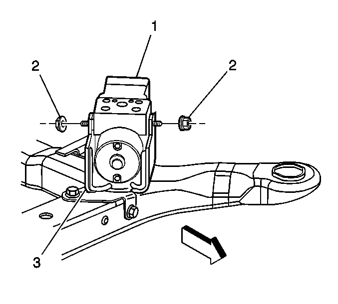
- Loosen the two mounting nuts (2) in order to allow removal of the brake pressure modulator valve (1) from the bracket (3).
- Remove the brake line retainers from the frame.
- Remove the left transaxle mount. Refer to Transmission Mount Replacement - Left Side .
- Remove the frame. Refer to Frame Replacement in Frame and Underbody.
- Remove the front transaxle mount bracket with mount attached. Refer to Transmission Mount Bracket Replacement - Front .
- Remove the right and left drive axles from the transaxle. Refer to Wheel Drive Shaft Replacement in Wheel Drive Shafts.
- Disconnect the transmission oil cooler hoses from the transaxle. Refer to Transmission Fluid Cooler Hose/Pipe Replacement .
- Remove the transaxle fluid filler tube. Refer to Transmission Fluid Filler Tube and Seal Replacement .
- Remove the torque converter cover. Refer to Torque Converter Cover Replacement .
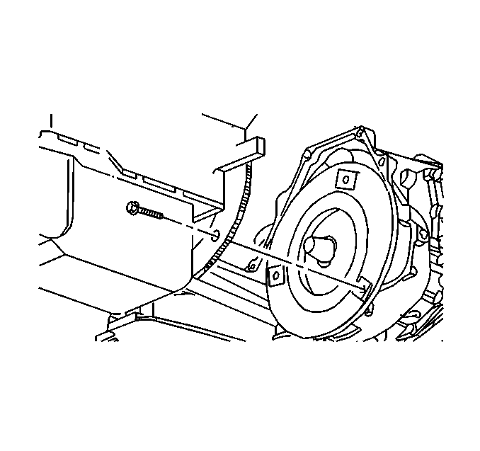
- Mark the flywheel to converter relationship to ensure proper reassembly. Remove the flywheel to torque converter bolts.
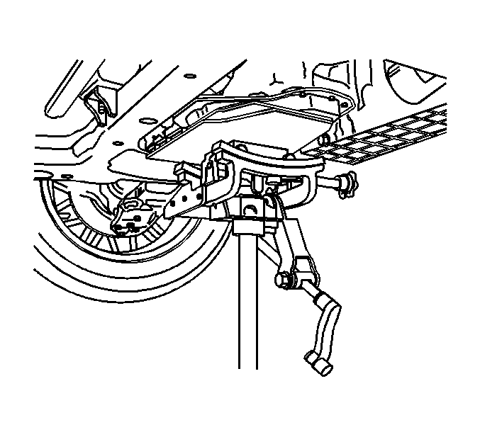
- Support transaxle using an appropriate transaxle jack.
- Disconnect vehicle speed sensor electrical connector.
- Remove the torque strut bracket to transaxle bolts.
- Remove the torque strut bracket to engine bolts.
- Remove the torque strut bracket.
- Remove the engine to transaxle case bolt (6) which is only accessible through right wheel opening.
- Remove the remaining transaxle to engine bolt (1).
- Remove the transaxle from vehicle using an appropriate transaxle jack.
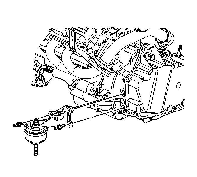
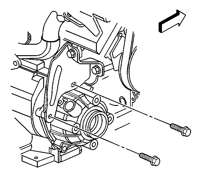
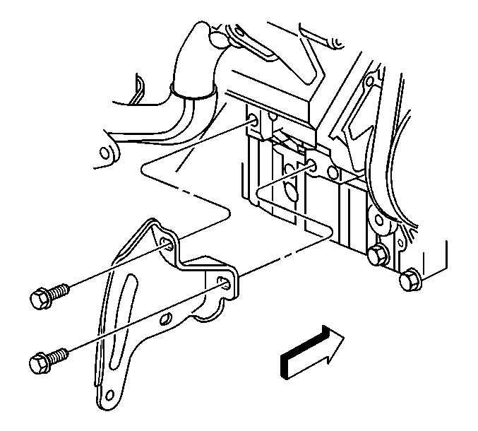
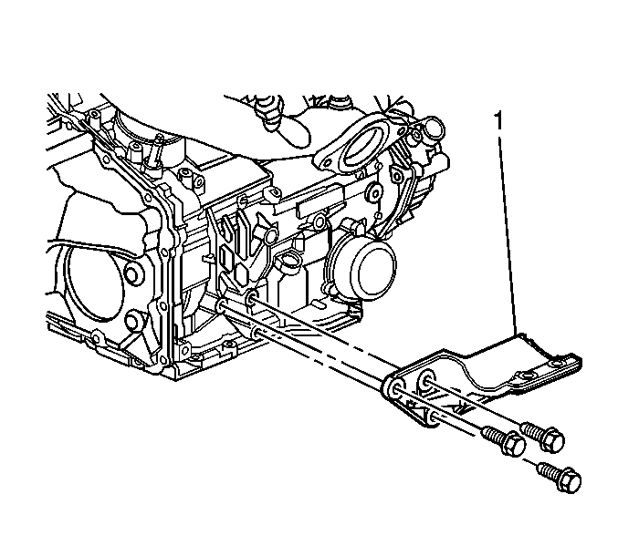
- Remove the rear transaxle bracket (1) from the transaxle.
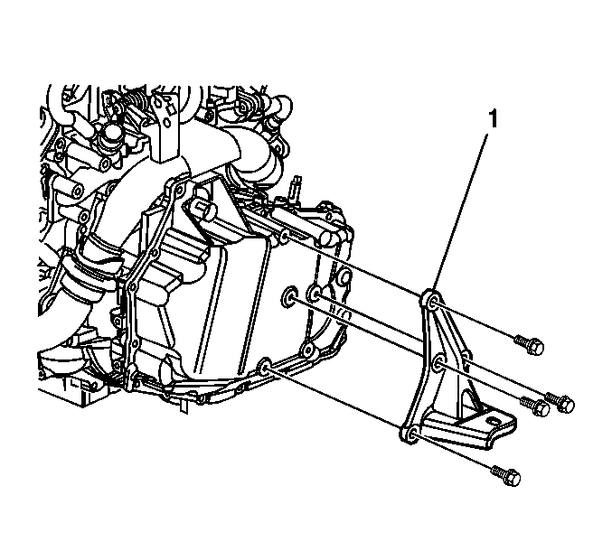
- Remove the left transaxle bracket (1) from the transaxle.
- Flush the transmission cooler and lines. Refer to Transmission Fluid Cooler Flushing and Flow Test .
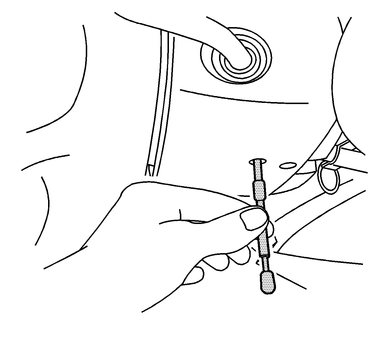
Notice: The wheels of the vehicle must be straight ahead and the steering column in the LOCK position before disconnecting the steering column or intermediate shaft from the steering gear. Failure to do so will cause the SIR coil assembly to become uncentered, which may cause damage to the coil assembly.
Caution: Failure to disconnect the intermediate shaft from the rack and pinion steering gear stub shaft can result in damage to the steering gear or to the intermediate shaft. This damage may cause loss of steering control, which could result in an accident and possible personal injury.

Installation Procedure
- Install the left transaxle bracket (1) to the transaxle.
- Install the left transaxle bracket bolts.
- Install the rear transaxle bracket (1) to the transaxle.
- Install the rear transaxle bracket bolts.
- Install the transaxle into the vehicle and align the engine alignment dowels (1 and 5).
- Install the transaxle case to engine bolts (1 and 6).
- Install the torque strut bracket.
- Install the torque strut bracket to engine bolts.
- Install the torque strut bracket to transaxle bolts.
- Connect vehicle speed sensor electrical connector.
- Remove the transaxle jack
- Install the flywheel to torque converter bolts.
- Install the torque converter cover. Refer to Torque Converter Cover Replacement .
- Install the transaxle fluid filler tube. Refer to Transmission Fluid Filler Tube and Seal Replacement .
- Connect the transmission oil cooler hoses to the transaxle. Refer to Transmission Fluid Cooler Hose/Pipe Replacement .
- Install the left and the right drive axle into the transaxle. Refer to Wheel Drive Shaft Replacement in Wheel Drive Shafts.
- Install the front transaxle mount bracket with mount attached. Refer to Transmission Mount Bracket Replacement - Front .
- Install the frame. Refer to Frame Replacement in Frame and Underbody.
- Install the left transaxle mount. Refer to Transmission Mount Replacement - Left Side .
- Position the brake pressure modulator valve (1) into the bracket (3).
- Install the brake line retainers onto the frame.
- Install the power steering gear mounting bolts.
- Install the power steering line retainers onto the frame.
- Install the power steering gear heat shield. Refer to Steering Gear Heat Shield Replacement in Power Steering System.
- Connect the intermediate shaft to the power steering gear.
- Install the intermediate shaft lower pinch bolt.
- Install both of the inner wheelhouse fillers (2). Refer to Front Bumper Fascia Extension Replacement in Bumpers.
- Install the front air deflector. Refer to Front Air Deflector Replacement in Body Front End.
- Install the front tire and wheel assembly. Refer to Tire and Wheel Removal and Installation in Tires and Wheels.
- Lower the vehicle.
- Install the upper transaxle case to engine bolts (2-5).
- Remove the engine support fixture.
- Install the range selector cable bracket and cable.
- Install the range selector cable onto the range selector lever.
- Check adjustment of the range selector cable. Re-adjust as needed. Refer to Range Selector Lever Cable Adjustment .
- Install ground cable and bolt (1) to transaxle.
- Connect the transaxle electrical connector C100 (2).
- Install the wiring harness (3) into the wiring harness retainer (1) on the transaxle.
- Install the air cleaner assembly. Refer to Air Cleaner Assembly Replacement in Engine Controls - 3.8L.
- Connect the negative battery cable. Refer to Battery Negative Cable Disconnection and Connection in Engine Electrical.
- Remove the J 42640 from the steering column.
- Fill the transaxle to the proper level. Refer to Fluid Capacity Specifications .
- Inspect the transaxle fluid level. Refer to Transmission Fluid Check .
- Inspect for fluid leaks.
- Reset the TAP values. Refer to Transmission Adaptive Functions.
- Check the front end alignment.
- Road test the vehicle and check for transaxle leaks.

Notice: Use the correct fastener in the correct location. Replacement fasteners must be the correct part number for that application. Fasteners requiring replacement or fasteners requiring the use of thread locking compound or sealant are identified in the service procedure. Do not use paints, lubricants, or corrosion inhibitors on fasteners or fastener joint surfaces unless specified. These coatings affect fastener torque and joint clamping force and may damage the fastener. Use the correct tightening sequence and specifications when installing fasteners in order to avoid damage to parts and systems.
Tighten
Tighten the left transaxle bracket bolts to 110 N·m (81 lb ft).

Tighten
Tighten the rear transaxle bracket bolts to 63 N·m (46 lb ft).

Tighten
Tighten the lower transaxle bolts to 75 N·m (55 lb ft).

Tighten
Tighten the torque strut bracket to engine bolts to 65 N·m (48 lb ft).

Tighten
Tighten the torque strut bracket to transaxle bolts to 36 N·m (26 lb ft).

Important:
• Align the mark made on the torque converter with the mark made on the flywheel made in the disassembly unless installing a new converter. • Tighten all the torque converter to flywheel bolts twice.
Tighten
Tighten the flywheel to torque converter bolts to 63 N·m (47 lb ft).
Important: Use care when installing the right side drive axle into the transaxle case. The splined shaft of the drive axle can easily cut or distort the seal.


Tighten
Tighten the two nuts (2) to 10 N·m (89 lb in).

Tighten
Tighten the bolts to 75 N·m (55 lb ft).

Caution: When installing the intermediate shaft make sure that the shaft is seated prior to pinch bolt installation. If the pinch bolt is inserted into the coupling before shaft installation, the two mating shafts may disengage. Disengagement of the two mating shafts will cause loss of steering control which could result in personal injury.
Tighten
Tighten the bolt to 45 N·m (33 lb ft).


Tighten
Tighten the transaxle bolts to 75 N·m (55 lb ft).

Tighten
Tighten the range selector cable bracket nuts to 25 N·m (18 lb ft).

Tighten
Tighten the ground cable bolt to 17 N·m (13 lb ft).


Important: It is recommended that transmission adaptive pressure (TAP) information be reset.
Resetting the TAP values using a scan tool will erase all learned values in all cells. As a result, The ECM, PCM or TCM will need to relearn TAP values. Transmission performance may be affected as new TAP values are learned.