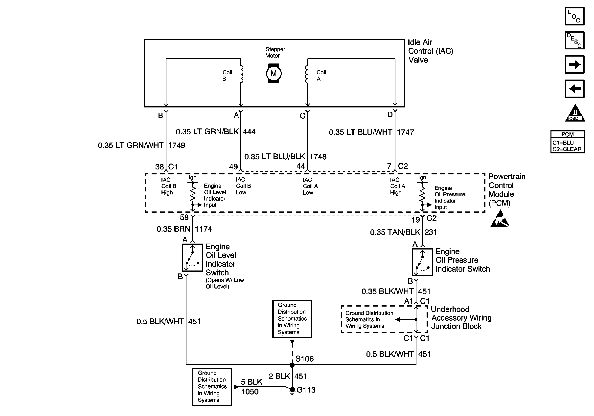
Refer to Engine Controls Schematics
IAC, Engine Oil Level/Pressure Switch

for wiring diagram.
Circuit Description
The low oil pressure sensor is normally closed. When oil pressure increases is above 1 to 4.5 psi the switch contacts open. The PCM supplies 12 volts to the oil pressure input circuit. With low oil pressure the 12 volts is pulled low to ground. This diagnostic tests for a open condition of the oil pressure switch circuit. If the engine has been off long enough for engine temperature to drop by 10°C, then a shorted (low oil pressure) condition of the circuit should be observed prior to engine running. If the engine has not been cranked and oil pressure has been detected. DTC P1189 will set.
Conditions for Running the DTC
| • | Codes P0117, P0118 and P1114 not set. |
| • | Ignition ON. |
| • | Engine OFF. |
| • | Engine temperature 10°C less than last key OFF temperature. |
Conditions for Setting the DTC
Circuit open for 10 seconds
Action Taken When the DTC Sets
| • | The Malfunction Indicator Lamp (MIL) will not illuminate. |
| • | No message will be displayed. |
Conditions for Clearing the MIL/DTC
| • | A History DTC will clear after forty consecutive warm-up cycles with no failures of any non-emission related diagnostic test. |
| • | A current DTC will clear when the diagnostic runs and does not fail. |
| • | Use a scan tool to clear DTCs. |
Diagnostic Aids
Check the oil pressure sensor input and ground circuits for an intermittent open or poor oil pressure sensor terminal contact. With the ignition ON and the engine OFF the oil pressure display on the scan tool should indicate LOW. An open sensor/circuit would indicate HIGH with the engine OFF.
This DTC only tests the oil pressure circuit for an open condition.
If the DTC cannot be duplicated and is determined to be intermittent, reviewing the Failure Records can be useful in determining when the DTC was last set. Also refer to Testing for Intermittent Conditions and Poor Connections in Wiring Systems.
Test Description
An example test description follows:
-
Checking to see if the fault is present. Low should be displayed with the engine not running.
-
Checking to see if the oil pressure switch or wiring is at fault.
-
Checking to see if the oil pressure switch input circuit or the PCM is at fault.
Step | Action | Value(s) | Yes | No |
|---|---|---|---|---|
1 | Did you perform the Powertrain On-Board Diagnostic (OBD) System Check? | -- | ||
Does the scan tool indicate low oil pressure? | -- | Go to Diagnostic Aids | ||
Does the scan tool indicate oil pressure low? | -- | |||
Is the resistance the same or less than the value specified? | 5 ohms | |||
5 | Repair the open in either the oil pressure sensor input circuit or the oil pressure sensor ground circuit. Refer to Wiring Repairs . Did you find and correct the condition? | -- | -- | |
6 | Inspect for poor connections at the harness connector of the oil pressure sensor connector. Refer to Testing for Intermittent Conditions and Poor Connections and Connector Repairs in Wiring Systems. Did you find and correct the condition? | -- | ||
7 | Inspect for poor connections at the harness connector of the PCM. Refer to Testing for Intermittent Conditions and Poor Connections and Connector Repairs in Wiring Systems. Did you find and correct the condition? | -- | ||
8 | Replace the oil pressure sensor. Did you complete the replacement? | -- | -- | |
9 |
Important: Perform the set up procedure for the PCM. Replace the PCM. Refer to Powertrain Control Module Replacement/Programming . Did you complete the replacement? | -- | -- | |
10 |
Does the DTC reset? | -- | System OK |
