For 1990-2009 cars only
Removal Procedure
- Remove engine appearance cover replacement. Refer to LINK.
- Remove the evaporative emission canister purge solenoid valve. Refer to Evaporative Emission Canister Purge Solenoid Valve Replacement.
- Release the power brake booster vacuum pipe. Refer to LINK.
- Remove the manifold absolute pressure sensor. Refer to Manifold Absolute Pressure Sensor Replacement.
- Remove the turbocharger control solenoid valve. Refer to LINK.
- Remove the oil level indicator and tube. Refer to Oil Level Indicator Tube Replacement.
- Release the charge air cooler outlet air hose. Refer to LINK.
- Remove the intake manifold brace. Refer to LINK.
- Remove the fuel feed pipe plastic. Refer to Fuel Feed Pipe Replacement.
- Remove the fuel feed pipe metal. Refer to Front Bumper Fascia Center Support Bracket Replacement.
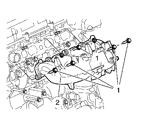
- Remove the 7 fasteners (1) from the intake manifold (2).

Installation Procedure
- Install the intake manifold.
- Install the fuel feed pipe metal. Refer to Front Bumper Fascia Center Support Bracket Replacement.
- Install the fuel feed pipe plastic. Refer to Fuel Feed Pipe Replacement.
- Install the intake manifold brace. Refer to LINK.
- Install the charge air cooler outlet air hose. Refer to LINK.
- Install the oil level indicator and tube. Refer to Oil Level Indicator Tube Replacement.
- Install the turbocharger control solenoid valve. Refer to LINK.
- Install the manifold absolute pressure sensor. Refer to Manifold Absolute Pressure Sensor Replacement.
- Install the power brake booster vacuum pipe. Refer to LINK.
- Install the evaporative emission canister purge solenoid valve. Refer to Evaporative Emission Canister Purge Solenoid Valve Replacement.
- Install engine appearance cover replacement. Refer to LINK.

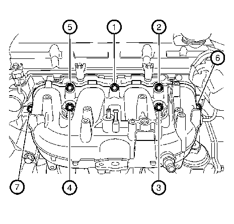
Install the fasteners in sequence and tighten to 25 N·m (18 lb ft).
