Tools Required
J 39400-A Halogen Leak Detector
Removal Procedure
- Recover the refrigerant from the A/C system. Refer to Refrigerant Recovery and Recharging .
- Drain the cooling system. Refer to Cooling System Draining and Filling.
- Remove the wiper motor module assembly. Refer to Windshield Wiper System Module Replacement .
- Set the HVAC controls in the vent setting to close the defroster door.
- Remove the blower motor. Refer to Blower Motor Replacement .
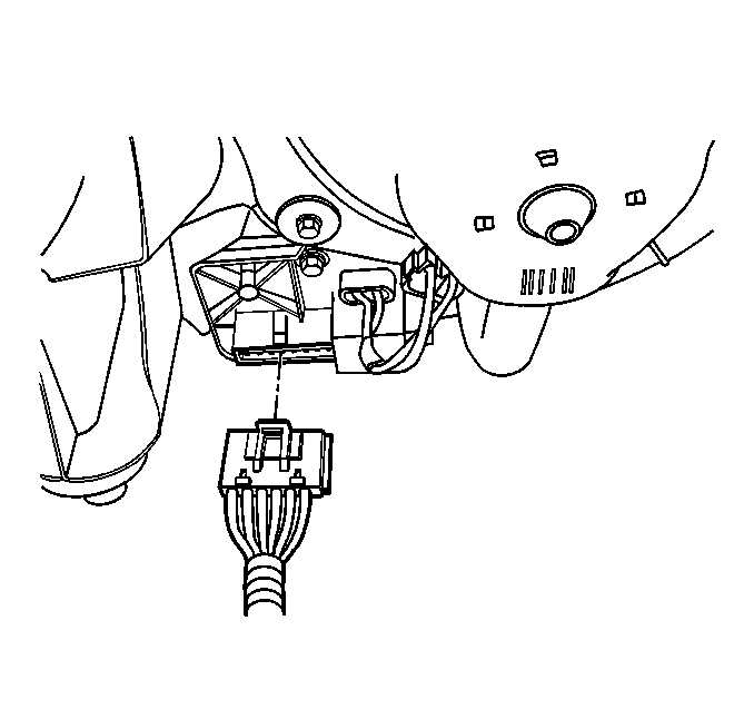
- Disconnect the electrical connector from the blower motor resistor.
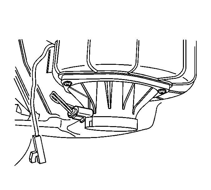
- Disconnect the electrical connector from the evaporator temperature sensor.
- Disconnect all of the HVAC electrical actuator connectors.
- Remove the I/P carrier. Refer to Instrument Panel Carrier Replacement .
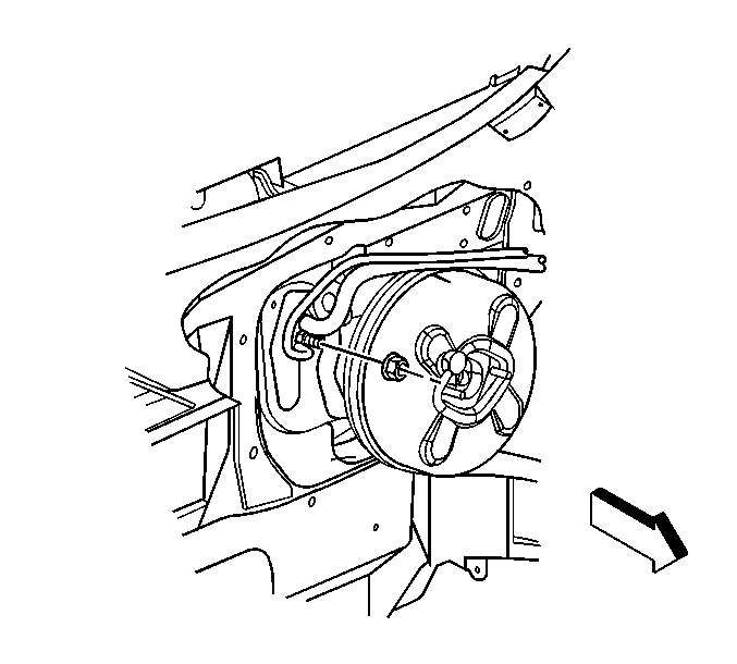
- Remove the evaporator outlet tube nut.
- Disconnect the evaporator outlet and inlet tubes from the TXV.
- Disconnect the heater inlet hose from the heater core. Refer to Heater Inlet Hose Replacement .
- Disconnect the heater outlet hose from the heater core. Refer to Heater Outlet Hose Replacement .
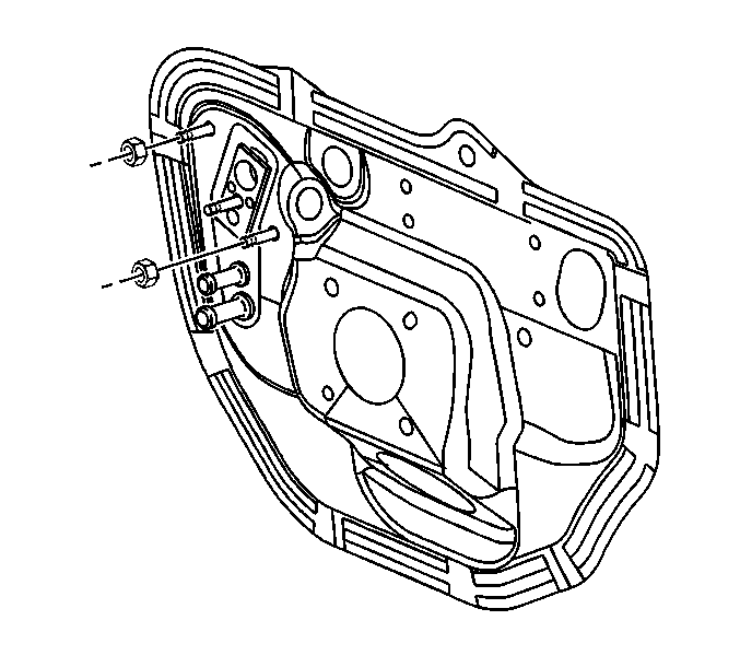
- Remove the HVAC module to dash panel sound barrier nuts.
- Remove the HVAC module assembly from the cowl.
Important: The defroster door must be closed to allow clearance during defroster duct removal.


Installation Procedure
- Install the HVAC module assembly to the cowl.
- Install the HVAC module assembly to dash panel sound barrier nuts.
- Install the heater outlet hose to the heater core. Refer to Heater Outlet Hose Replacement .
- Install the heater inlet hose to the heater core. Refer to Heater Inlet Hose Replacement .
- Install new sealing washers to the evaporator inlet and outlet tubes. Refer to Sealing Washer Replacement .
- Connect the evaporator inlet tube to the evaporator outlet tube.
- Connect the evaporator inlet and outlet tubes to the TXV.
- Install the evaporator outlet tube nut at the TXV.
- Install the I/P carrier. Refer to Instrument Panel Carrier Replacement .
- Connect all of the HVAC electrical actuator connectors.
- Connect the electrical connector to the evaporator temperature sensor.
- Connect the electrical connector to the blower motor resistor.
- Install the blower motor. Refer to Blower Motor Replacement
- Tighten the HVAC module assembly to dash panel sound barrier nuts.
- Install the wiper motor module assembly. Refer to Windshield Wiper System Module Replacement .
- Fill the coolant system. Refer to Cooling System Draining and Filling .
- Evacuate and recharge the A/C system. Refer to Refrigerant Recovery and Recharging
- Leak test the fittings of the component using the J 39400-A .
Important: Ensure proper alignment of the HVAC module assembly and HVAC module drain through the cowl.

Do not tighten the HVAC module assembly nuts at this time.

Notice: Use the correct fastener in the correct location. Replacement fasteners must be the correct part number for that application. Fasteners requiring replacement or fasteners requiring the use of thread locking compound or sealant are identified in the service procedure. Do not use paints, lubricants, or corrosion inhibitors on fasteners or fastener joint surfaces unless specified. These coatings affect fastener torque and joint clamping force and may damage the fastener. Use the correct tightening sequence and specifications when installing fasteners in order to avoid damage to parts and systems.
Tighten
Tighten the nut to 16 N·m (12 lb ft).


Tighten
Tighten the nuts to 10 N·m (89 lb in).
