Removal Procedure
Tools Required
Caution: Unless directed otherwise, the ignition and start switch must be in the OFF or LOCK position, and all electrical loads must be OFF before servicing
any electrical component. Disconnect the negative battery cable to prevent an electrical spark should a tool or equipment come in contact with an exposed electrical terminal. Failure to follow these precautions may result in personal injury and/or damage to
the vehicle or its components.
- Disconnect
the negative battery cable.
- Remove drain and recover coolant. Refer to
Cooling System Draining and Filling
in Engine Cooling.
- Recover the refrigerant if equipped with A/C. Refer to Air Conditioning.
- Remove the left sound insulator.
- Disconnect the clutch push rod from the pedal assembly (manual
transmission only).
- Disconnect the heater hose at the thermostat housing.
- Disconnect the radiator inlet (upper) hose.
- Remove the air cleaner assembly.
- Remove the coolant fan. Refer to
Engine Cooling Fan Replacement
in Engine Cooling.
- Remove the compressor/condenser hose assembly at the compressor
and discard the O-rings, if the vehicle is A/C equipped. Refer to Air Conditioning.
- Disconnect the vacuum hoses from the front of the engine.
- Remove the following electrical connections:
| • | The A/C compressor, if equipped |
| • | The IAC and TP sensor at the throttle body |
| • | The Intake Air Temperature (IAT) sensor |
| • | The EVAP Canister Purge solenoid |
| • | The negative battery cable from the transmission |
| • | The Electronic Ignition Coil and Module assembly |
| • | The two Engine Coolant Temperature sensors |
| • | The Oil Pressure sensor/switch |
| • | The O2S (Oxygen sensor) |
| • | The Crankshaft Position sensor |
| • | The back up Lamp switch and position the harness aside |
| • | The camshaft position sensor |
- Remove the power brake vacuum hose from the throttle body.
- Remove the throttle cable.
- Remove the throttle cable bracket.
- Remove the power steering bolts.
- Remove the power steering
pump. Position the pump aside with the lines attached.
Caution: Remove the fuel tank cap and relieve the fuel system pressure before
servicing the fuel system in order to reduce the risk of personal injury.
After you relieve the fuel system pressure, a small amount of fuel may be
released when servicing the fuel lines, the fuel injection pump, or the connections.
In order to reduce the risk of personal injury, cover the fuel system components
with a shop towel before disconnection. This will catch any fuel that may
leak out. Place the towel in an approved container when the disconnection
is complete.
- Disconnect the fuel lines. Refer to
Fuel Hose/Pipes Replacement - Chassis
.
- Disconnect the shift cables. Refer to Engine Controls.
- Disconnect the clutch actuator line. Refer to Manual Transaxle.
- Remove the exhaust manifold.
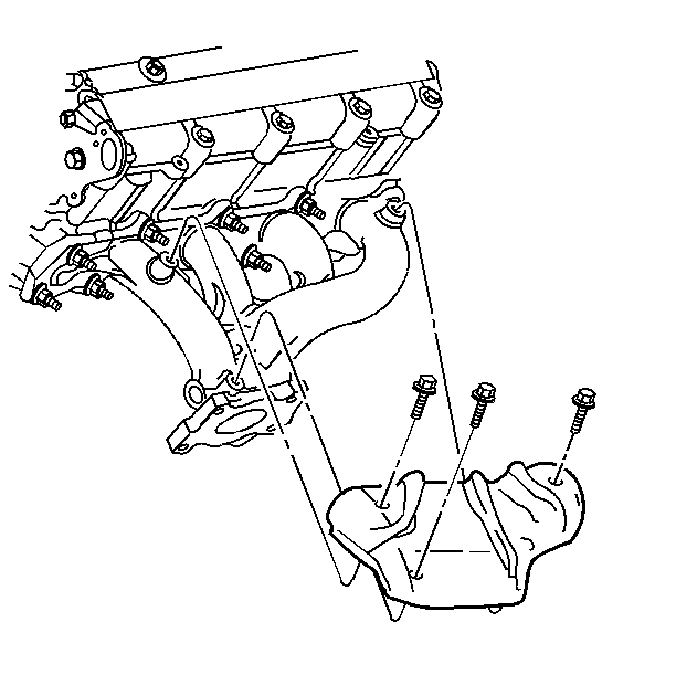
- Remove the heat shield.
- Disconnect the radiator outlet (lower) hose from the radiator.
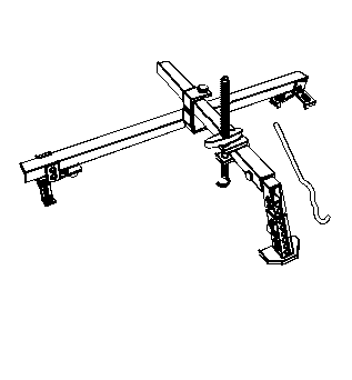
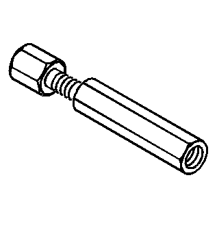
- Install the J 28467-360
.
- Remove the one bolt attaching the coolant recovery tank. Position
the tank aside with the hoses connected.
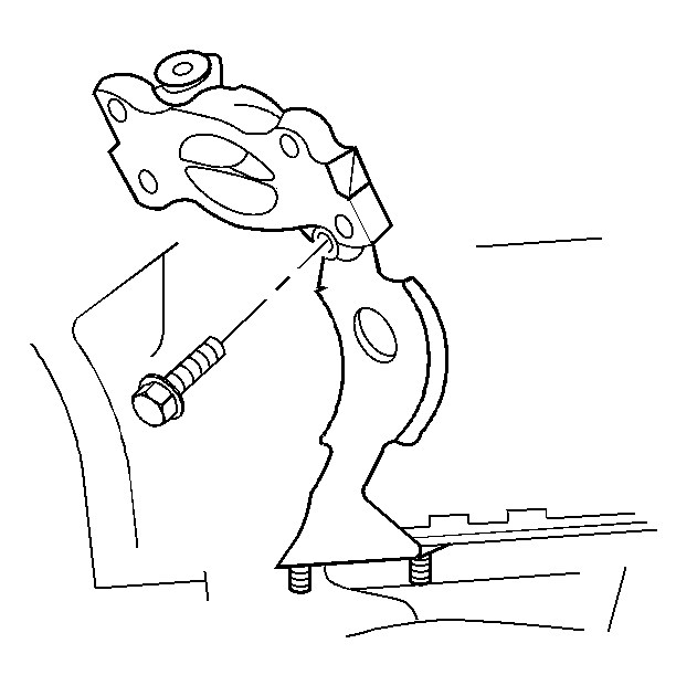
- Remove the engine mount assembly. Refer to
Engine Mount Replacement
.
- Raise and support the vehicle. Refer to
Lifting and Jacking the Vehicle
.
- Remove the front wheel and tire assemblies. Refer to
Wheel Removal
in Tire and Wheels.
- Remove the right splash shield.
- Remove the following electrical connections:
| • | Both of the front ABS wheel speed sensors |
- Remove the engine mount strut. Refer to
Engine Mount Strut Replacement
.
- Remove the transmission mount. Refer to
Transmission Mount Replacement
in Manual Transmission - M5 and MK.
- Separate the ball joints from the steering knuckles. Refer to
Steering Knuckle Replacement
in Front Suspension.
- Remove the suspension supports and the stabilizer shaft as an
assembly. Refer to
Stabilizer Shaft Replacement
in Front Suspension.
- Disconnect the heater outlet hose from the radiator outlet pipe.
- Remove the axle shaft from the transmission and intermediate shaft
(manual transmission only). Position the axle shaft aside. Refer to Drive
Axle.
- Remove the flywheel housing cover.
- Position suitable support below the engine and lower the car into
the support.
- Mark the threads on the support fixture hooks in order to duplicate
the setting when reinstalling the engine.
- Remove the engine support fixture J-hooks.
- Raise the vehicle slowly off of the engine and transmission assembly.
It may be necessary to move the engine/transmission assembly rearward in order
to clear the intake manifold.
- Separate the engine from the transmission.
Installation Procedure
Important: Make certain the bolts are in their correct locations.
- Assemble the engine to the transmission.
- Position the engine and the transmission assembly under the engine
compartment.
- Slowly lower the vehicle over the assembly until the transmission
mount is indexed.
- Install the bolt.
- Install the J 28467-360
adjust to the previous setting.
- Install the engine mount assembly. Refer to
Engine Mount Replacement
.
- Install the transmission mount. Refer to
Transmission Mount Replacement
in Manual Transmission - M5 and MK.
- Raise the vehicle off of the support.
- Install the axle shafts to the transmission. Refer to Drive Axle.
- Connect the heater outlet hose to the radiator outlet pipe.
- Install the suspension supports. Refer to
Stabilizer Shaft Replacement
in Front Suspension.
- Install the stabilizer shaft assembly. Refer to
Stabilizer Shaft Replacement
in Front Suspension.
- Install the ball joint nuts. Refer to
Steering Knuckle Replacement
in Front Suspension.
- Install the engine strut mount. Refer to
Engine Mount Strut Replacement
.
- Connect the following electrical connections:
| • | Both front ABS wheel speed sensors |
- Install the flywheel housing cover.
- Connect the lower radiator hose.
- Install the right splash shield.
- Install the front tires and wheels. Refer to
Wheel Installation
in Tire and Wheels.
- Lower the vehicle.
- Remove the J 28467-A
.
- Install the coolant recovery tank. Refer to
Radiator Surge Tank Replacement
in Engine Cooling.
- Install the following electrical connections:
| • | The A/C compressor, if equipped. |
| • | The IAC and TP sensor at the throttle body. |
| • | The EVAP Canister Purge solenoid. |
| • | The ground connections. |
| • | The negative battery cable to the transmission. |
| • | The two Engine Coolant Temperature sensors. |
| • | The Oil Pressure sensor/switch. |
| • | The O2S (Oxygen Sensor). |
| • | The crankshaft position sensor. |
| • | The Backup Light switch. |
| • | The Electronic Ignition Coil and Module assembly. |
| • | The camshaft position sensor. |
- Connect the vacuum hoses.
- Connect the compressor/condenser hose assembly to the compressor,
if A/C equipped. Refer to Air Conditioning.
- Install the clutch actuator line. Refer to Manual Transaxle.
- Install the shift cables. Refer to Manual Transaxle.
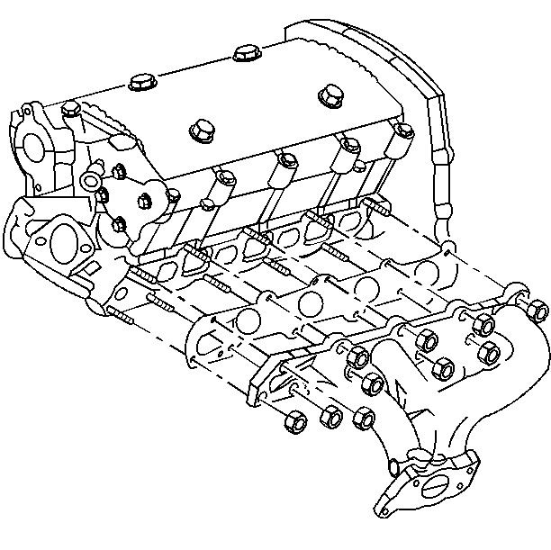
- Install the exhaust manifold.
- Install the heat shield.
- Connect the fuel lines. Refer to Fuel Hose and Pipes-Engine Compartment
Fuel Pipes.
- Connect the positive battery cable to the battery.
- Install the power steering
pump to the block. Refer to
Power Steering Pump Replacement
in Power Steering System.
- Install the power steering pump bolts. Refer to
Power Steering Pump Replacement
in Power Steering
System.
- Connect the vacuum hoses to intake manifold.
- Install the throttle cable bracket.
- Install the throttle cable. Refer to
Accelerator Control Cable Replacement
in Engine Controls.
- Install the coolant fan. Refer to
Engine Cooling Fan Replacement
in Engine Cooling.
- Install the air cleaner assembly.
- Install the radiator outlet (upper) hose.
- Fill the cooling system. Refer to
Cooling System Draining and Filling
in Engine Cooling.
- Install the left sound insulator and disconnect the clutch push
rod from the pedal assembly, on manual transmission only.
- Connect the heater hose at the thermostat housing.
- Fill the transmission with fluid. Refer to
Transmission Fluid Check
in Transmission.
- Fill engine oil.
- Connect the negative battery cable.
- If the vehicle is A/C equipped, evaluate, charge and leak test
the A/C system. Refer to Air Conditioning.
