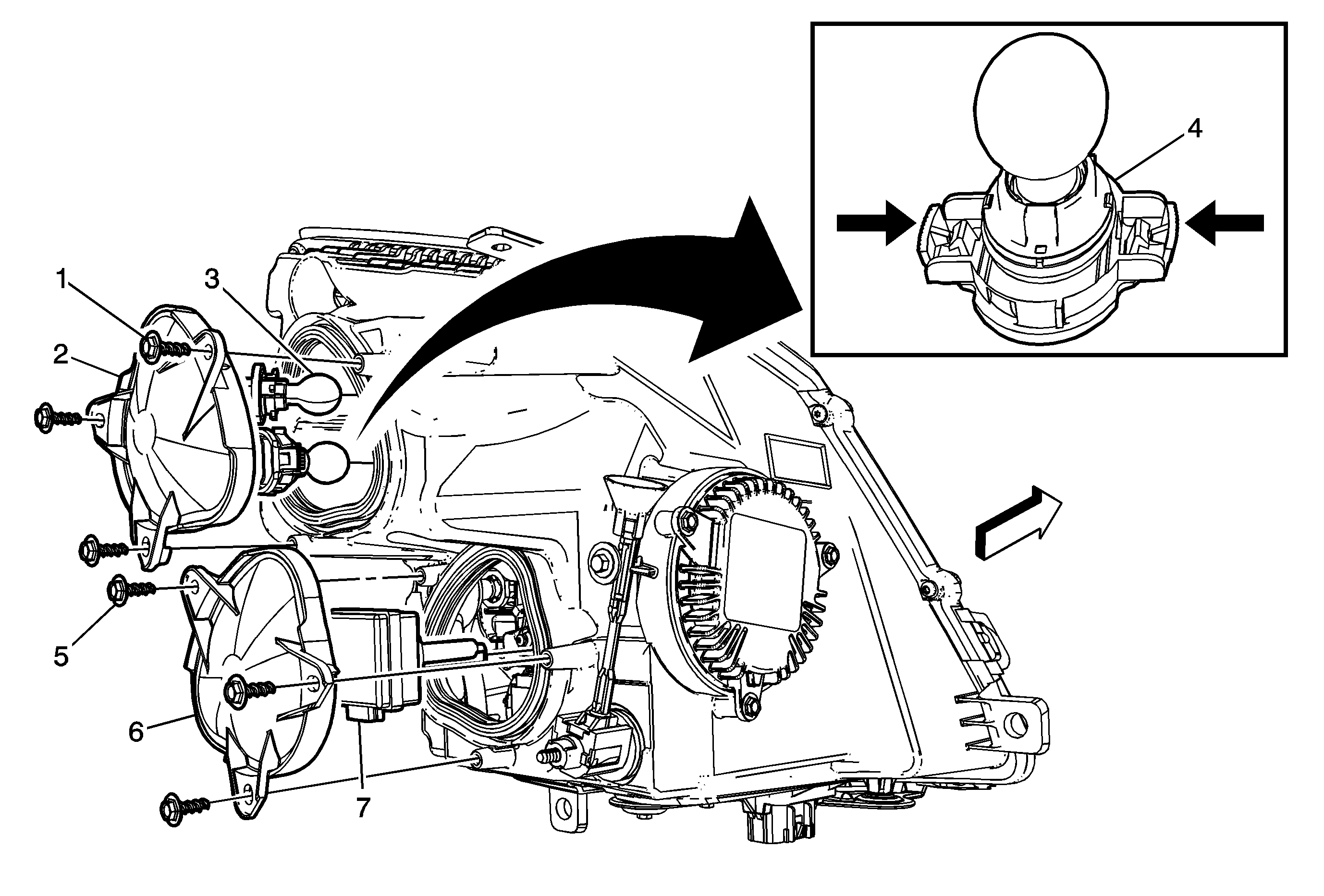
Headlamp Assembly or Headlamp Bulb and/or Cornering, Sidemarker, Park, Turn Signal Bulb Replacement TT6

Callout | Component Name | ||||
|---|---|---|---|---|---|
|
Warning: The high intensity discharge system produces high voltage and current. In order to reduce the risk of severe shocks and burns, the battery negative cable must be disconnected any time service work is being performed on or around the high intensity discharge system. Warning: The high intensity discharge system produces high voltage and current. To reduce the risk of severe shocks and burns:
Preliminary ProcedureRemove the headlamp capsule. Refer to Headlamp Capsule Replacement. | |||||
1 | Accessory Cap Screw (Qty: 3) Tip | ||||
2 | Accessory Cap Tip | ||||
3 | Turn Signal Lamp Bulb Warning: Refer to Halogen Bulb Warning in the Preface section. Procedure
| ||||
4 | Daytime Running Lamp Bulb (DRL) Warning: Refer to Halogen Bulb Warning in the Preface section. Procedure
| ||||
5 | Accessory Cap Screw (Qty: 3) Tip | ||||
6 | Accessory Cap Tip | ||||
7 | Headlamp Bulb with Ballast Warning: Refer to Halogen Bulb Warning in the Preface section. Procedure
| ||||
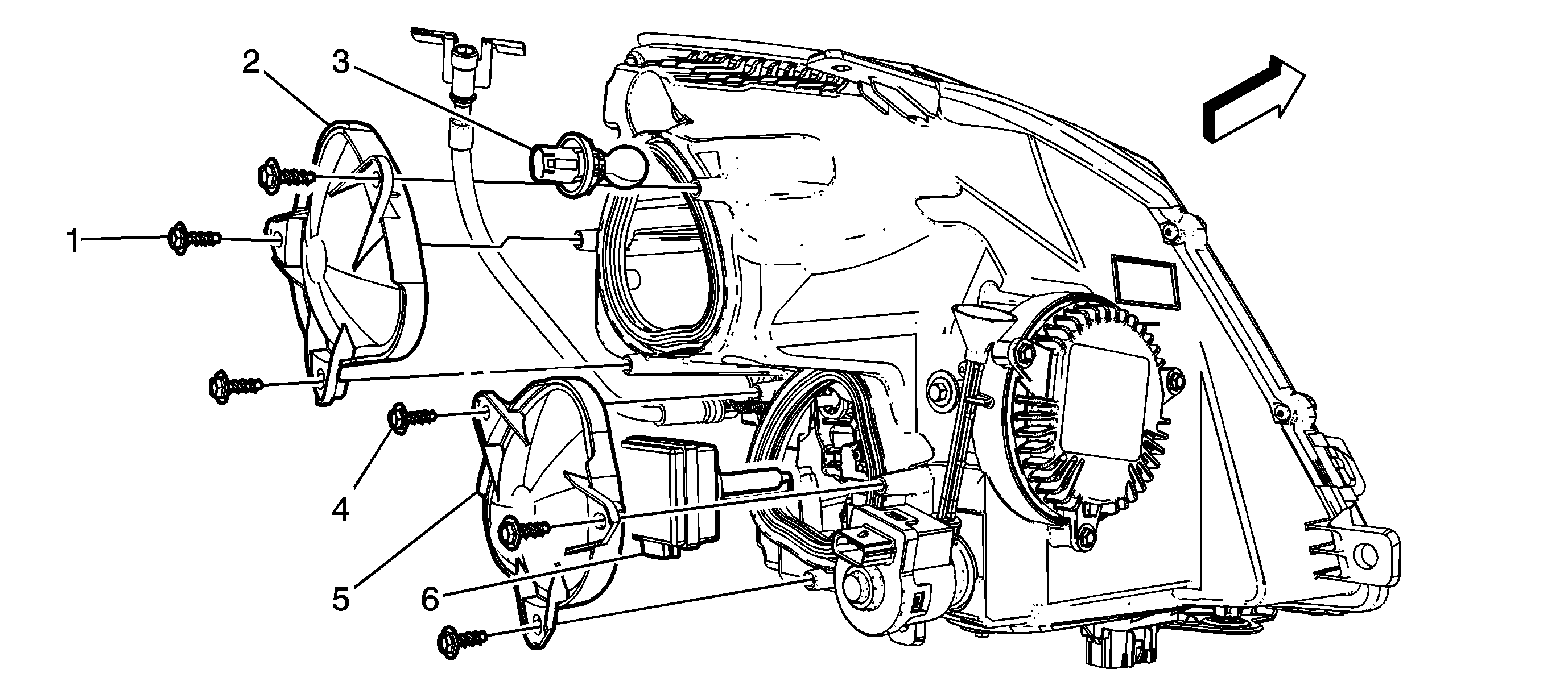
Headlamp Assembly or Headlamp Bulb and/or Cornering, Sidemarker, Park, Turn Signal Bulb Replacement TT7

Callout | Component Name | ||||
|---|---|---|---|---|---|
|
Warning: The high intensity discharge system produces high voltage and current. In order to reduce the risk of severe shocks and burns, the battery negative cable must be disconnected any time service work is being performed on or around the high intensity discharge system. Warning: The high intensity discharge system produces high voltage and current. To reduce the risk of severe shocks and burns:
Preliminary ProcedureRemove the headlamp capsule. Refer to Headlamp Capsule Replacement. | |||||
1 | Accessory Cap Screw (Qty: 3) Tip | ||||
2 | Accessory Cap Tip | ||||
3 | Directional Bulb Warning: Refer to Halogen Bulb Warning in the Preface section. Procedure
| ||||
4 | Accessory Cap Screw (Qty: 3) Tip | ||||
5 | Accessory Cap Tip | ||||
6 | Headlamp Bulb with HID Ballast Warning: Refer to Halogen Bulb Warning in the Preface section. Procedure
| ||||
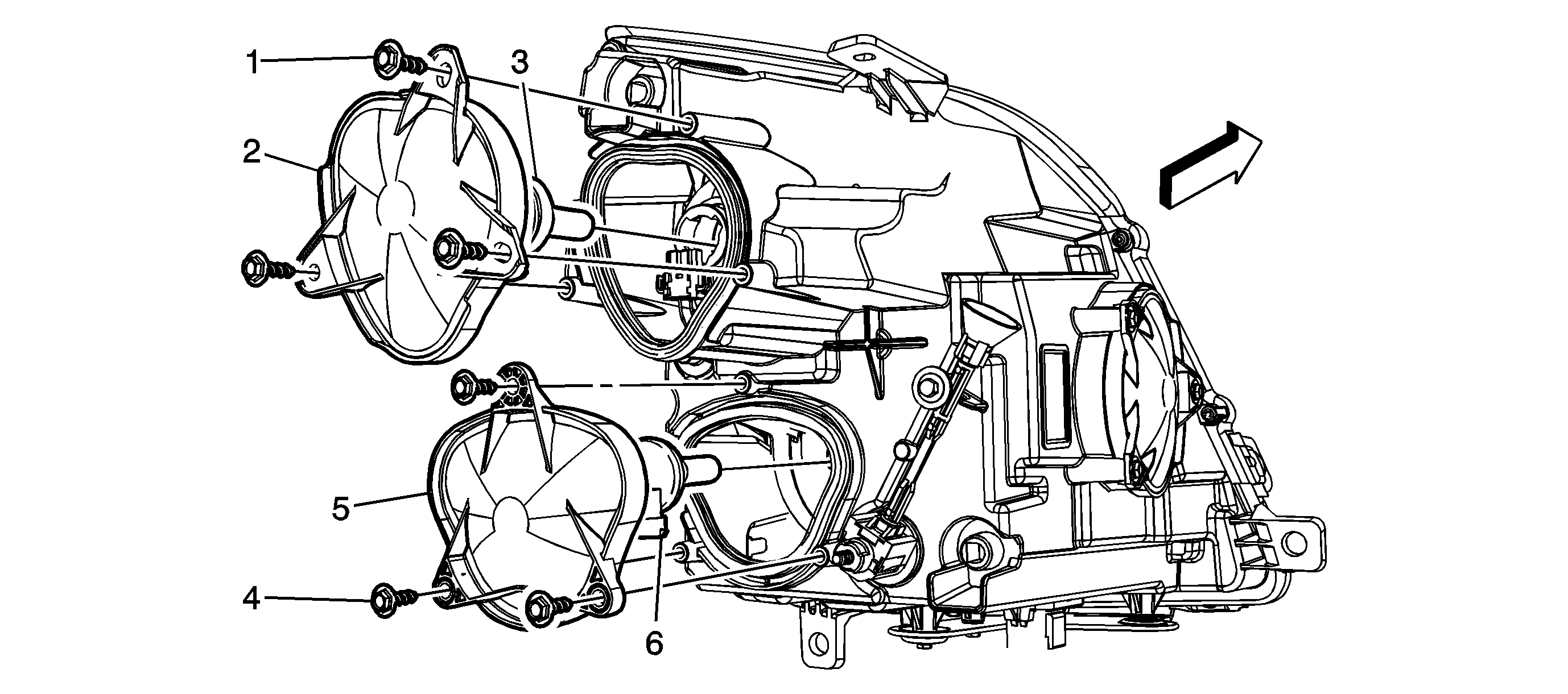
Headlamp Assembly or Headlamp Bulb and/or Cornering, Sidemarker, Park, Turn Signal Bulb Replacement TT8

Callout | Component Name | ||||
|---|---|---|---|---|---|
|
Warning: The high intensity discharge system produces high voltage and current. In order to reduce the risk of severe shocks and burns, the battery negative cable must be disconnected any time service work is being performed on or around the high intensity discharge system. Warning: The high intensity discharge system produces high voltage and current. To reduce the risk of severe shocks and burns:
Preliminary ProcedureRemove the headlamp capsule. Refer to Headlamp Capsule Replacement. | |||||
1 | Accessory Cap Screw (Qty: 3) Tip | ||||
2 | Accessory Cap Tip | ||||
3 | Directional Bulb Warning: Refer to Halogen Bulb Warning in the Preface section. Procedure
| ||||
4 | Accessory Cap Screw (Qty: 3) Tip | ||||
5 | Accessory Cap Tip | ||||
6 | Headlamp Bulb with HID Ballast Warning: Refer to Halogen Bulb Warning in the Preface section. Procedure
| ||||
Headlamp Assembly or Headlamp Bulb and/or Cornering, Sidemarker, Park, Turn Signal Bulb Replacement Minus TT6/TT7/TT8/T84/T85

Callout | Component Name |
|---|---|
Preliminary ProcedureRemove the headlamp capsule. Refer to Headlamp Capsule Replacement. | |
1 | Accessory Cap Screw Tip |
2 | Accessory Cap Tip |
3 | Low Beam Bulb Warning: Refer to Halogen Bulb Warning in the Preface section. Procedure
|
4 | Accessory Cap Screw Tip |
5 | Accessory Cap Tip |
6 | High Beam Bulb Warning: Refer to Halogen Bulb Warning in the Preface section. Procedure
|
