For 1990-2009 cars only
Tools Required
J 35268-A Camshaft/Front Main Seal Installer
Removal Procedure
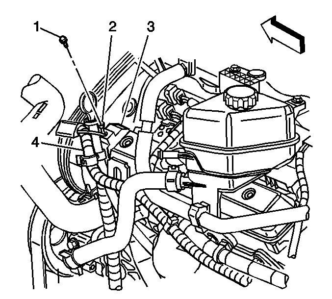
- If equipped with RPO code KA3, remove the bolt (1) securing the coolant heater ground lead (2) to the camshaft bearing cap (3).
- Remove the left camshaft cover. Refer to Camshaft Cover Replacement - Left Side .
- Remove the left camshaft drive sprockets. Refer to Camshaft Drive Sprocket Replacement .
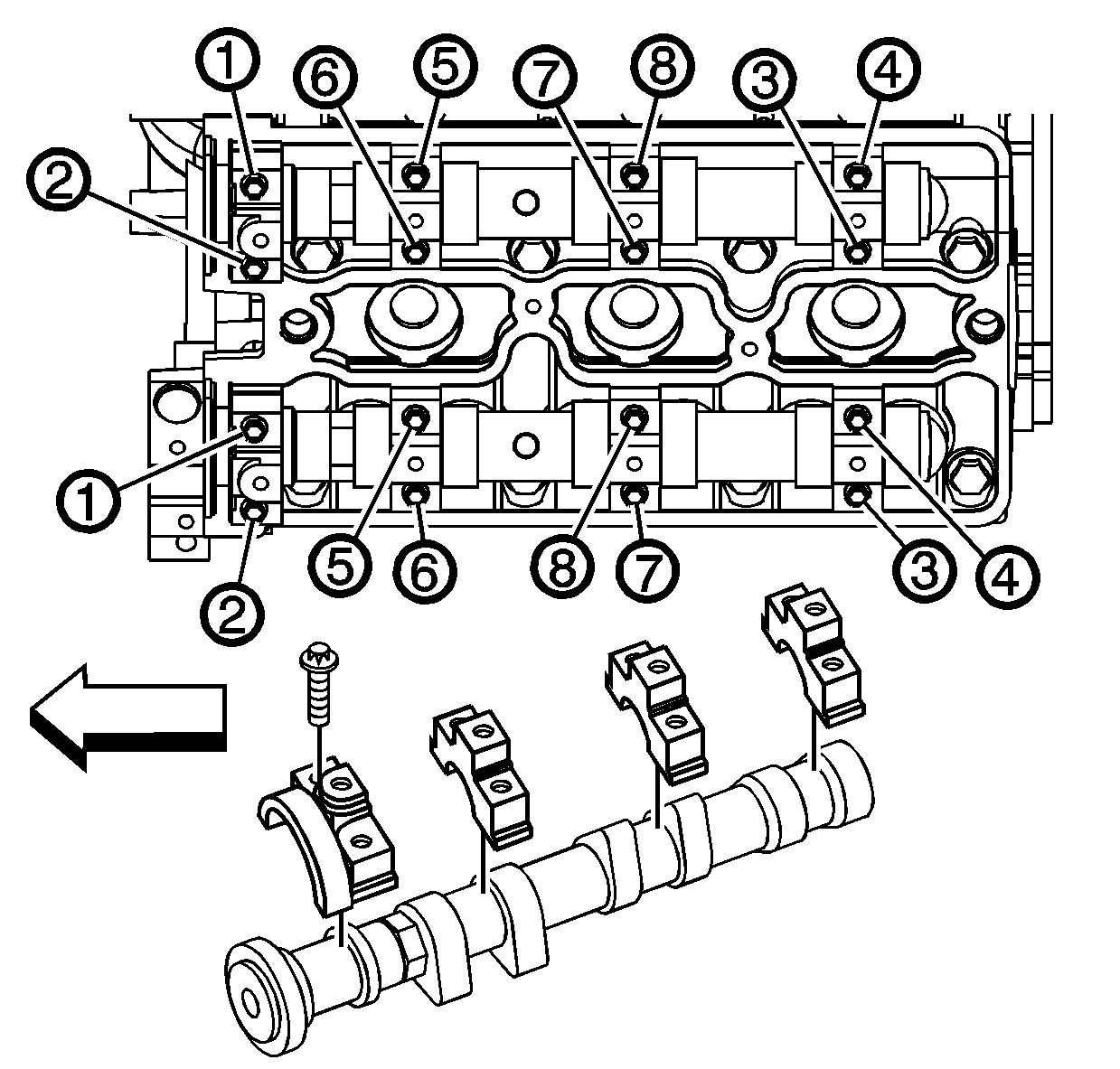
- Alternately loosen the camshaft bearing cap bolts a few turns at a time using the loosening sequence.
- Remove the camshaft bearing cap bolts.
- Remove the camshaft bearing caps. Note the code marks on the bearing caps (R1, R2, R3, etc.).
- Remove the camshafts from the cylinder head.
- Remove the camshaft seals.
- Clean all of the bearing surfaces.
- Clean all of the sealing surfaces.
- Clean and inspect the camshafts. Refer to Camshaft and Bearings Cleaning and Inspection .
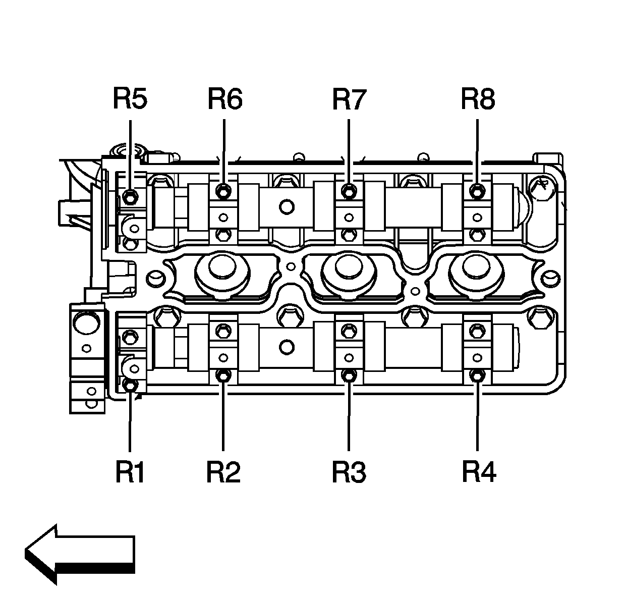
The bearing caps for the left cylinder head is marked with an R, followed by a number.
Installation Procedure
- Choose the correct camshaft to be installed.
- Lubricate the following with GM P/N 1052367 (Canadian P/N 992869), or equivalent:
- Install the camshafts to the cylinder head.
- Apply a small amount of GM P/N 1052942 (Canadian P/N 10953466), or equivalent on the forward edge of the front bearing caps to ensure an adequate seal between the bearing cap and the cylinder head.
- Install the camshaft bearing caps according to the identification marks.
- Install the camshaft bearing cap bolts.
- Alternately hand tighten the camshaft bearing cap bolts in sequence a few turns at a time until all caps are fully seated.
- Tighten the camshaft bearing cap bolts in sequence to 8 N·m (71 lb in).
- Coat the lip of the camshaft seal with a small amount of clean engine oil to aid in installation.
- Use the J 35268-A to tap the camshaft seal into place.
- Install the left camshaft drive sprockets. Refer to Camshaft Drive Sprocket Replacement .
- Install the left camshaft cover. Refer to Camshaft Cover Replacement - Left Side .
- If equipped with RPO code KA3, install the bolt (1) securing the coolant heater ground lead (2) to the camshaft bearing cap (3).
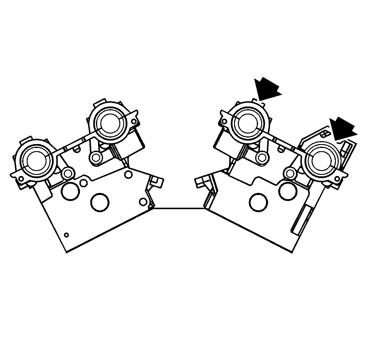
Camshaft Identification
| • | 2.6L (LY9) |
| - | The intake camshaft is stamped with the letter "F" next to bearing 1. |
| - | The exhaust camshaft is stamped with the letter "N" next to bearing 1. |
| • | 3.2L (LA3) |
| - | The intake camshaft is stamped with the letter "G" next to bearing 1. |
| - | The exhaust camshaft is stamped with the letter "J" next to bearing 1. |
| • | Camshaft bearing surfaces |
| • | Camshaft lobes |
Important: Ensure the pin on the exhaust camshaft is approximately in the 1 o'clock position and/or that the pin on the intake camshaft is approximately in the 8 o'clock position to allow for minimal load on the camshaft when installing the bearing caps.
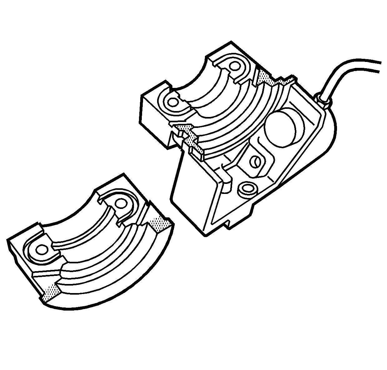
Important: DO NOT allow the sealer to get into the oil journal of the cap.

Notice: Refer to Fastener Notice in the Preface section.
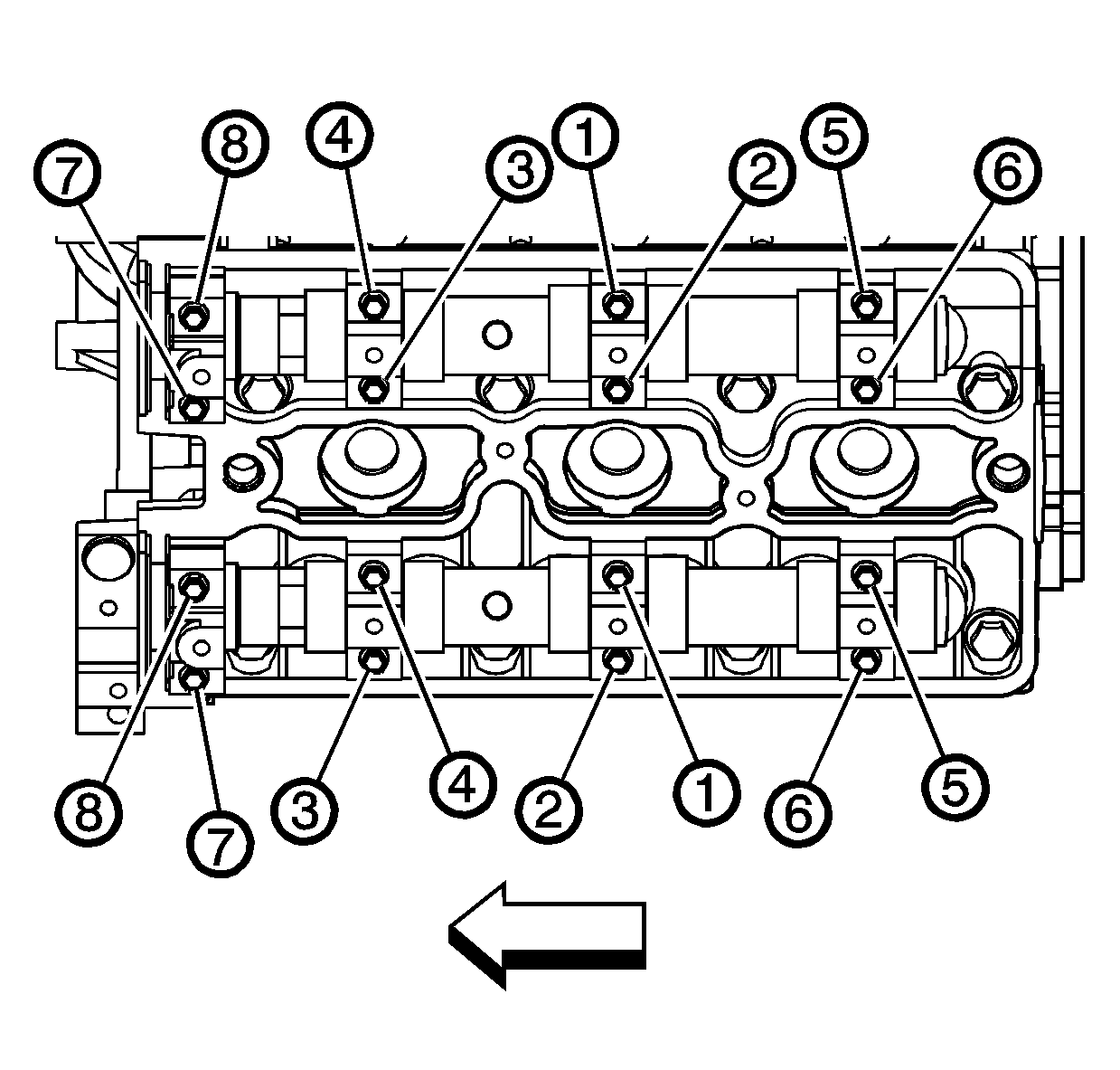
Tighten
Ensure the camshaft seal is fully and evenly seated.

Tighten
Tighten the coolant heater ground lead bolt to 9 N·m (80 lb in).
