For 1990-2009 cars only
Removal Procedure
- Remove the left closeout/insulator panel. Refer to Instrument Panel Insulator Panel Replacement - Left Side in Instrument Panel, Gages and Console.
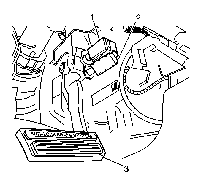
- Twist the upper switch (1) counterclockwise and remove the switch.
- Disconnect the upper switch electrical connector.
Installation Procedure
- Connect the upper switch (1) electrical connector.
- Install the upper switch (1) into the upper retainer.
- Twist the switch clockwise until fully seated.
- Adjust the switch. Refer to Torque Converter Clutch/Cruise Control Release Switch Replacement .
- Install the left closeout/insulator panel. Refer to Instrument Panel Insulator Panel Replacement - Left Side in Instrument Panel, Gages and Console.
Important: When installing the brake pedal switches, ensure that the brake pedal remains in the full up or at rest position.
Important: The release switch assembly and the stoplamp switch assembly cannot be adjusted until after the brake booster pushrod is assembled to brake pedal assembly. Incorrect adjustment may cause the cruise control system to not work properly.
