Removal Procedure
Tools Required
Refer to J 37088-A , Fuel Line Quick-Connect Separator Tool Set
The following procedure covers disassembly and inspection of the complete fuel supply system. If the fuel system is contaminated, it can be cleaned. The extent of fuel system contamination can usually be determined during disassembly.
- Disconnect the negative battery terminal.
- Relieve the fuel system pressure, refer to Fuel Pressure Relief Procedure .
- Remove the in-line fuel filter, refer to In-Line Fuel Filter Replacement .
- Inspect for contamination of the in-line fuel filter.
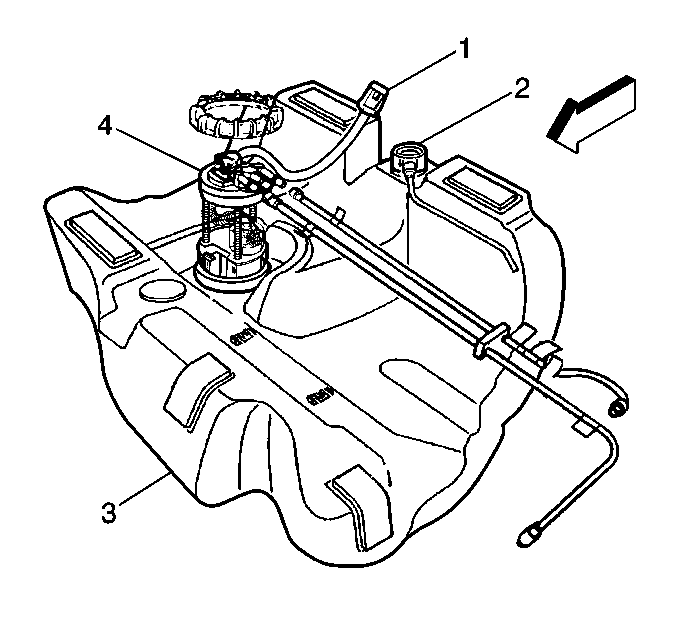
- Drain fuel tank (1), refer to Fuel Tank Replacement (Draining) .
- Remove fuel tank, refer to Fuel Tank Replacement .
- Locate the tank in a suitable work area away from heat, flame or other source of ignition.
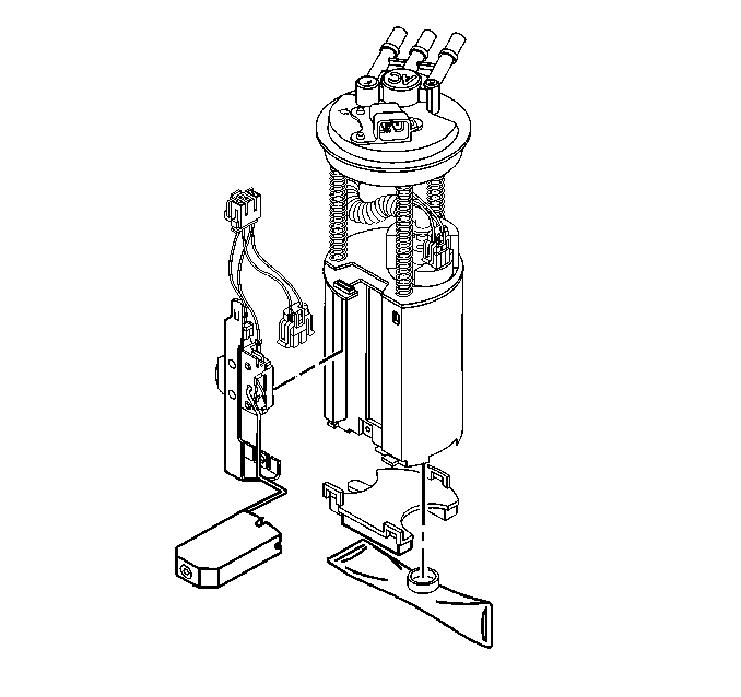
- Remove the modular fuel sender assembly (4), refer to Fuel Sender Assembly Replacement .
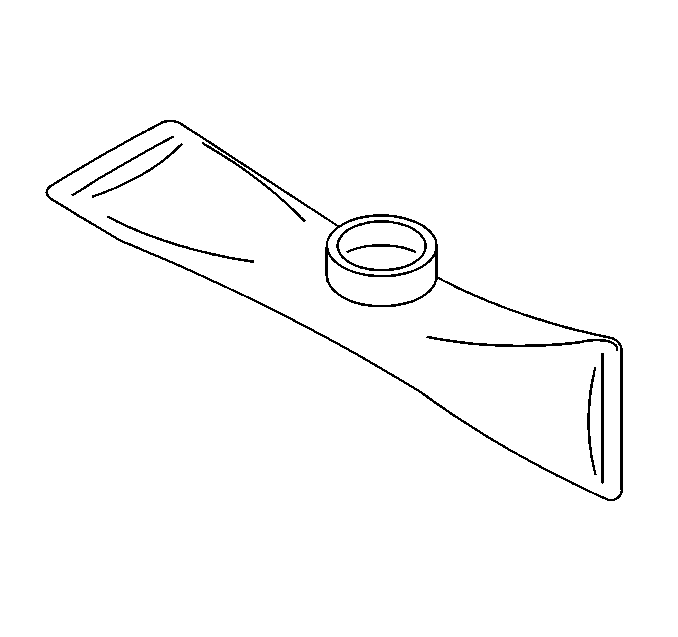
- Inspect fuel sender strainer. If strainer is contaminated, it must be replaced and the fuel tank should be cleaned.
- Inspect the fuel pump inlet for dirt and debris. If found, fuel sender should be replaced.
- Flush fuel tank with running hot water for at least five minutes.
- Pour water out of fuel sender assembly opening.
- Rock the tank to be sure that removal of water from tank is complete.
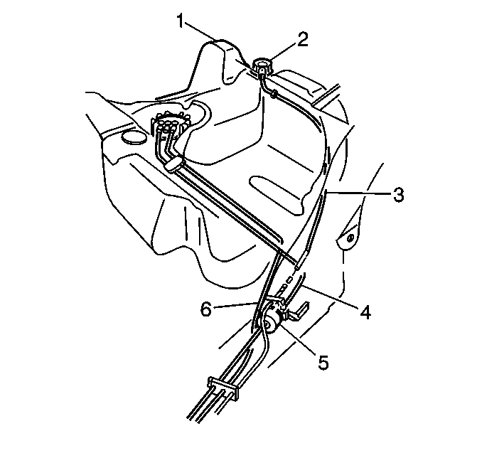
- Remove the fuel feed (1), fuel return (2) and at engine compartment.
- Grasp both ends of the fuel feed pipe connection and twist 1/4 turn in each direction to loosen any dirt in quick connect fittings.
- Blow out dirt from quick connect fittings, using compressed air.
- Squeeze plastic tabs of male end connector of fuel filter.
- Pull connection apart.
- Grasp both ends of one fuel return pipe connection and twist 1/4 turn in each direction to loosen any dirt in quick connect fittings.
- Blow out dirt from quick connect fittings, using compressed air.
- Squeeze plastic tabs of male end connector of fuel filter.
- Pull connection apart.
- Insert J 37088-A tool into female connector, then push inward to release male connector.
- Apply air pressure to fuel pipes in the opposite direction from normal fuel flow.
- Wipe off male pipe ends. Inspect all connectors for dirt and burrs, using a clean shop towel.
- Clean components/assemblies as required.
- Replace components/assemblies as required.

If filter is plugged or contaminated, replace it after cleaning fuel pipes.
Important: If nylon fuel feed or return pipes become kinked, and cannot be straightened, they must be replaced.
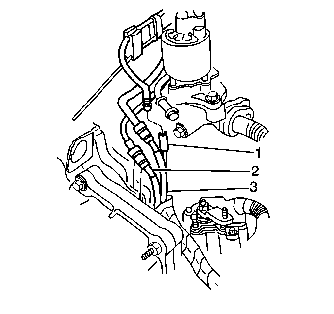
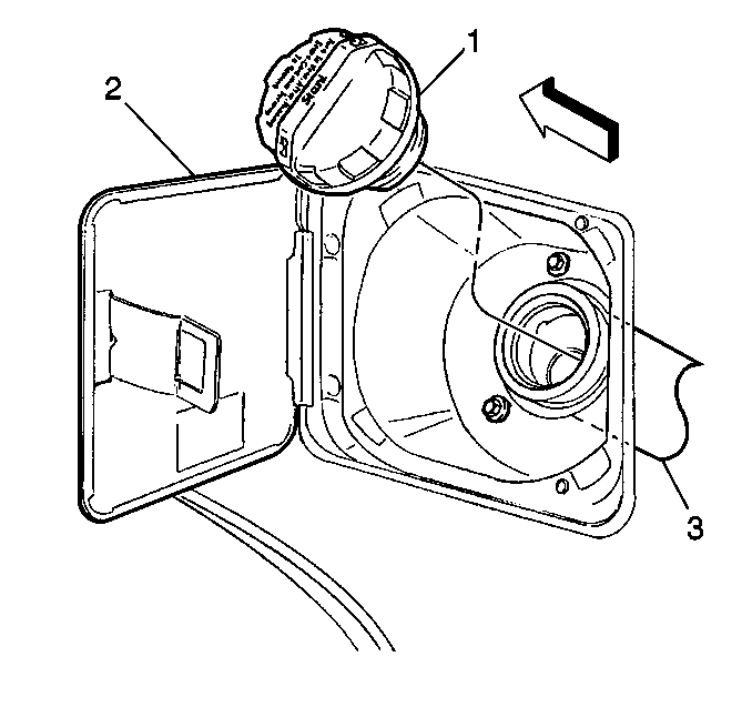
If necessary remove the (3) EVAP Pipe.
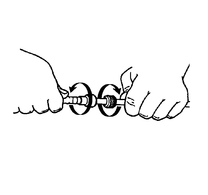
Caution: Wear safety glasses when using compressed air in order to prevent eye injury.
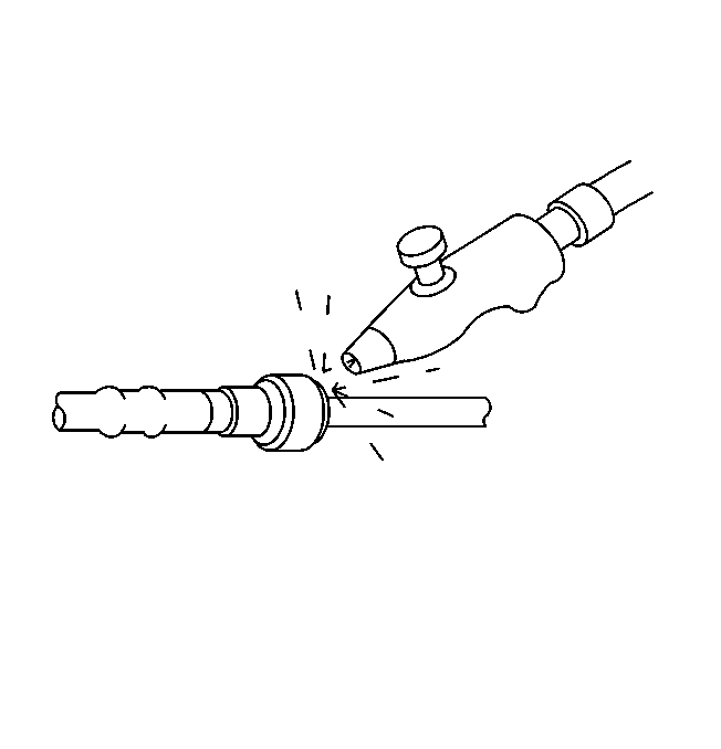
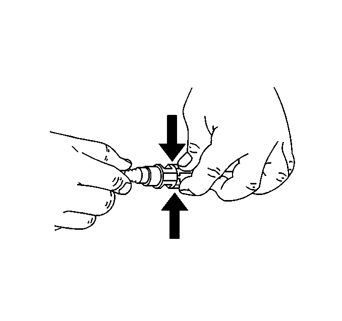
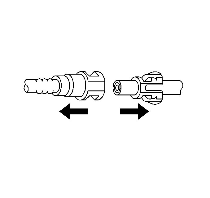

Caution: Wear safety glasses when using compressed air in order to prevent eye injury.


Repeat for other fitting.
Notice: Use an emery cloth in order to remove rust or burrs from the fuel pipe. Use a radial motion with the fuel pipe end in order to prevent damage to the O-ring sealing surface.
Installation Procedure
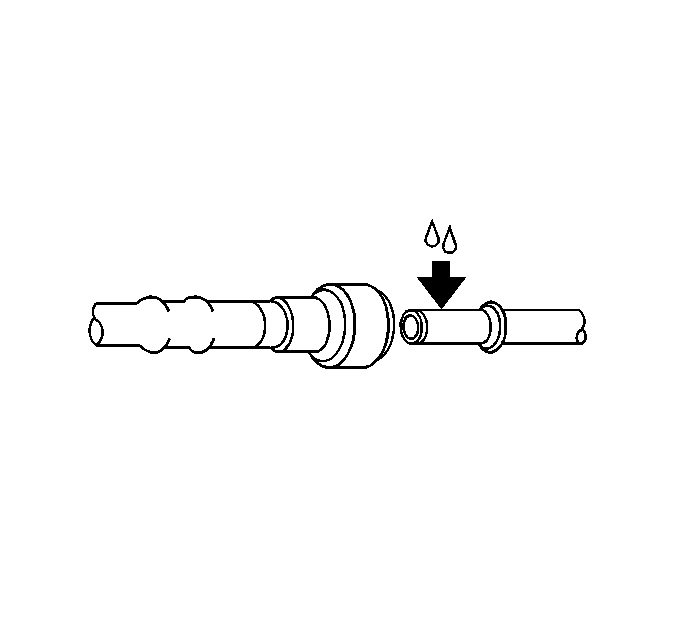
Caution: Always apply a few drops of clean engine oil to the male pipe ends before connecting the fuel pipe fittings in order to reduce the risk of fire and personal injury. This will ensure proper reconnection and prevent a possible fuel leak. During normal operation, the O-rings located in the female connector will swell and may prevent proper reconnection if not lubricated.
- Apply a few drops of clean engine oil to the male tube ends of the fuel feed and return engine pipes.
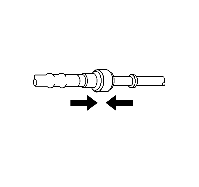
- Connect the fuel feed and fuel return pipe quick-connect fittings
- Push connectors together to cause the retaining tabs/fingers to snap into place.
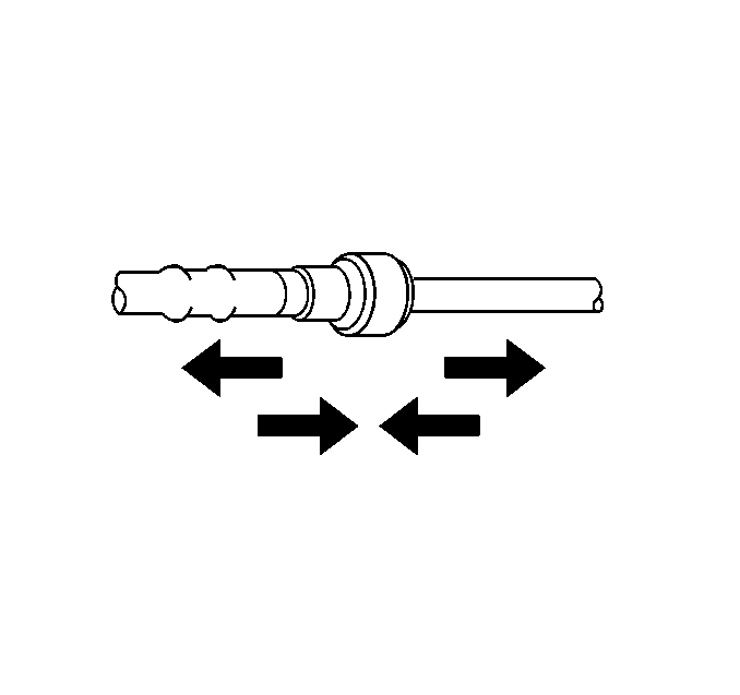
- Once installed, pull on both ends of each connection to make sure they are secure.
- Install fuel sender assembly. Refer to Fuel Sender Assembly Replacement .
- Install fuel filter. Refer to In-Line Fuel Filter Replacement .
- Install fuel tank. Refer to Fuel Tank Replacement .



| 7.1. | Turn ignition switch to On for 2 seconds. |
| 7.2. | Turn the ignition switch to Off for 5 seconds. |
| 7.3. | Turn the ignition switch On. |
| 7.4. | Check for fuel leaks. |
