Fuel Supply System Specifications
Fuel
The fuel must meet ASTM Standard: D4814 (U.S.), CGSB 3.5-M93 (Canada).
Octane Requirements
Minimum Octane requirement: 91 [(R+M)/2] (pump) octane where R=research octane number and M=motor octane number.
Gasoline with Alcohol
Notice: Do Not spill fuel containing alcohol on the vehicle. Alcohol can cause damage to the paint finish and the trim.
Methyl Tertiary-Butyl Ether (MTBE)
Fuel containing Methyl Tertiary-Butyl Ether (MTBE) may be used, providing there is no more than 15% alcohol by volume.
Ethanol
Fuel containing ethanol (ethyl) or grain alcohol may be used, providing that there is no more than 10% ethanol alcohol by volume.
Methanol
Notice: Do not use fuels containing methanol in order to prevent damage and corrosion to the fuel system.
Methylcyclopentadienyl Manganese Tricarbonyl (MMT)
If a vehicle is certified to meet California Emission Standards (indicated on the under-hood tune-up label), it is designed to operate on fuels that meet California specifications. If such fuels are not available in states adopting California emissions standards, a vehicle will operate satisfactorily on fuels meeting federal specifications, but emission control system performance may be affected. The malfunction indicator lamp on the instrument panel may turn on. The vehicle may also fail a smog-check test.
Some gasolines that are not reformulated for low emissions contain an octane-enhancing additive called methylcyclopentadienyl manganese tricarbonyl (MMT). General Motors does not recommend the use of such gasolines. If fuels containing MMT are used, spark plug life may be reduced, and emission control system performance can be affected. The malfunction indicator lamp on the instrument panel can turn on.
To provide cleaner air, all gasolines are now required to contain additives that will help prevent deposits from forming in the engine and fuel system. These additives will allow the emission system to function properly. Therefore, there does not need to be anything added to the fuel. In addition, gasolines containing oxygenates, such as ethers and ethanol, and reformulated gasolines may be available in the area to help clean the air. General Motors recommends that the above mentioned gasolines be used if they comply with specifications described earlier.
Fuel Supply System System Components
Fuel Tank
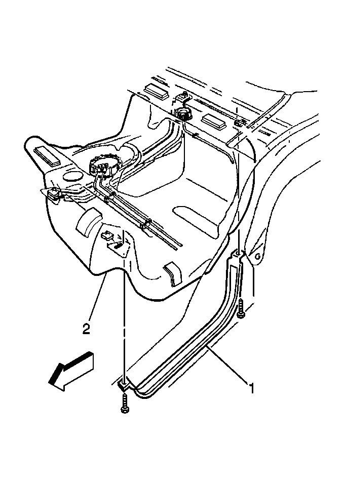
The fuel storage tank (2) is made of high density polyethylene and is located in front of the rear wheels. It is held in place by two metal straps (1) attached to the under body of the vehicle. The tank shape includes a sump to maintain a constant supply of fuel around the fuel pump strainer during low fuel conditions or aggressive maneuvers. The tank also contains a fuel vapor vent valve with roll-over protection. The vent valve also features a two phase vent calibration which increases fuel vapor flow to the canister when operating temperatures increase the tank pressure beyond an established threshold.
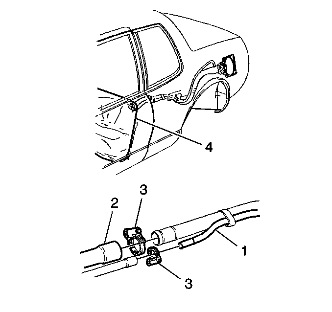
To help prevent refueling with leaded fuel, the fuel filler pipe (1) has a built-in restrictor and deflector. The opening in the restrictor will accept only the smaller unleaded gasoline fuel nozzle which must be fully inserted to bypass the deflector. The filler pipe is attached to the tank (4) by a section of hose (2) and two hose (3) clamps. The tank is vented during filling by an internal vent tube inside the filler pipe.
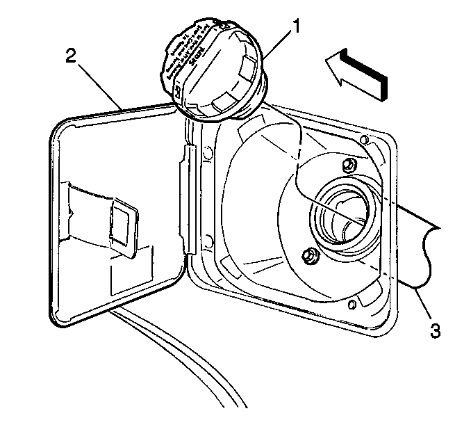
The fuel tank filler pipe (3) is equipped with a turn to vent screw on type cap (1) which incorporates a ratchet action to prevent over-tightening. The filler cap is located inside the fuel filler (2) door.
The turn to vent feature allows fuel tank pressure relief prior to removal. Instructions for proper use are imprinted on the cap cover. A vacuum safety relief valve is incorporated into this cap.
Notice: Use a fuel tank filler pipe cap with the same features as the original when a replacement is necessary. Failure to use the correct fuel tank filler pipe cap can result in a serious malfunction of the fuel system.
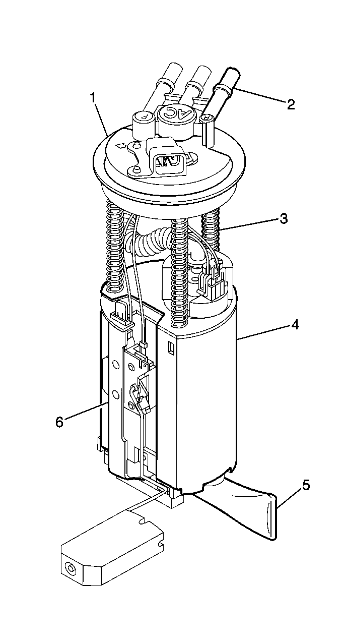
The modular fuel sender assembly mounts to the threaded opening of the plastic fuel tank with a multi-lipped seal and threaded retainer (nut). The spring loaded reservoir, containing the exterior inlet strainer, electric fuel pump and pump strainer, maintains contact with the tank bottom. This design provides:
| • | Optimum fuel level in the integral fuel reservoir during all fuel tank levels and driving conditions. |
| • | Improved tank fuel level measuring accuracy. |
| • | Improved coarse straining and added pump inlet filtering. |
| • | More extensive internal fuel pump isolation for noiseless operation. |
The modular fuel sender assembly consists of the following major components: A fuel sender cover assembly (1), a fuel sender, fuel pipes (above cover) (2), a fuel sender support assembly (3), a fuel pump, a fuel pump strainer, a fuel pump reservoir (4), a fuel sender strainer (5), and a fuel level sensor assembly (6).
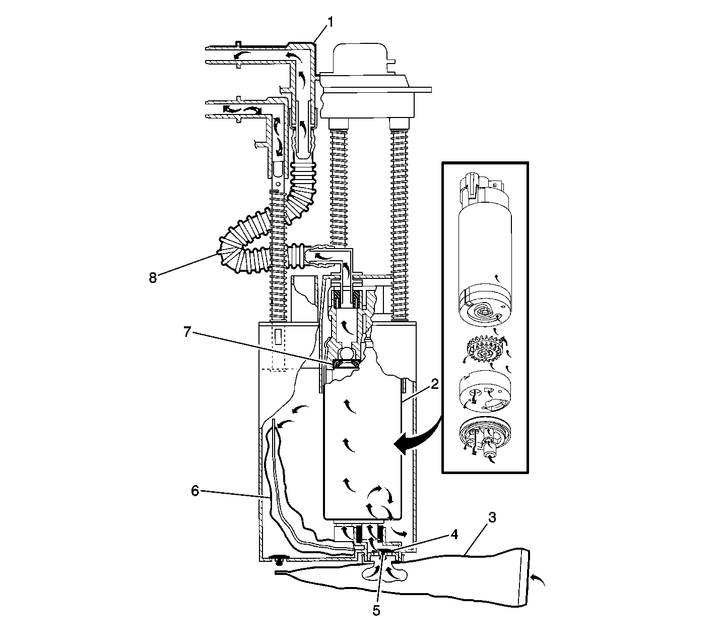
The modular fuel sender assembly maintains optimum fuel level in the reservoir (bucket). Fuel entering the reservoir (bucket) is drawn in by:
| • | The first stage of the GEN III turbine pump through the external strainer. |
| And/Or |
| • | The secondary umbrella valve (3), |
| Or |
| • | The return fuel pipe, whenever the level of fuel is below the top of the reservoir. |
The GEN III turbine fuel pump used in this system is part of the fuel sender assembly. The fuel pump lower connector assembly prevents the transmission of vibration and noise generated by the pump to the fuel tank.
Fuel enters the lower inlet port (4) (secondary umbrella valve located inside of lower inlet port) of the Gen III electric fuel pump (1) after being filtered by the external fuel strainer (2), and the fuel pump strainer (5). The initial function of the pump is to fill the reservoir.
The second stage separates vapor from the fuel in the pump. This vapor separation maximizes hot fuel handling and permits the vapor to return to the fuel tank at lower pressure and temperature. By creating positive fuel pressure, the pump then discharges the liquid fuel into the third stage of the pump. The pump outlet allows the fuel volume to flow through a check valve (6) into the fuel pump flex pipe. The check valve seat is molded inside the connector body. The check valve body and retainer are assembled into the connector body. The check valve restricts fuel back flow.
After the fuel pump flex pipe (7), the fuel exits the assembly through the fuel feed output fitting on the molded cover. The cover also contains a fuel return provision which connects to one of three hollow support pipes.
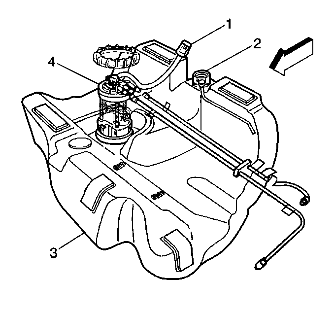
Two quick-connect pipe end fittings are molded onto the cover of the modular unit for ease of unit removal from the fuel tank. These quick-connect end fittings allow fuel feed and fuel return.
Electrical power to the fuel pump enters the unit by way of a connector (1) which is attached to the cover. An internal wire harness and connector assembly connects to the fuel pump and level sensor. The modular design adds additional functions that improve accuracy and ensure constant, steady fuel supply under all conditions. All components and subassemblies of the modular sender attach to a common cover and access the fuel tank through a single opening. The modular fuel sender assembly (4) is spring loaded to the bottom of the fuel tank. This bottom referencing permits continuous fuel pickup and accurate fuel level sensing. The reservoir assembly is the lower section of the modular unit which encases the GEN III turbine pump. A retainer attaches to the top of the reservoir. Fuel is captured and maintained in reservoir at a level sufficient to submerge the GEN III turbine pump.
A rubber bumper (pad) is assembled between the bottom of the reservoir and the fuel sender strainer. This promotes noise isolation by acting as a buffer between the reservoir bottom and the fuel tank and provides a fastening mechanism for the fuel level sensor assembly to the reservoir.
Two quick-connect pipe end fittings are molded onto the cover of the modular unit for ease of unit removal from the fuel tank. These quick-connect end fittings allow fuel feed and fuel return.
The tank (3) also contains a fuel vapor vent valve (2) with roll-over protection. The vent valve also features a two phase vent calibration which increases fuel vapor flow to the canister when operating temperatures increase the tank pressure beyond an established threshold.
The electric fuel pump is a GEN III turbine pump located inside the modular fuel sender. The electric fuel pump operation is controlled by the PCM through two fuel pump relays or by the oil pressure sensor.
There are two serviceable fuel strainers utilized in the modular fuel sender assembly. One is located at the bottom of the GEN III turbine pump (inside the reservoir) (1) and the second fuel strainer is external to the reservoir (3) and is positioned on the bottom of the fuel tank. Both strainers act as a coarse filter to: filter contaminants, separate water from fuel, and to provide a wicking action that helps draw fuel into the fuel pump.
Fuel stoppage at the strainer indicates that the fuel tank contains an abnormal amount of sediment or water. Therefore, the fuel tank should be removed, cleaned, and the filter strainer replaced. Refer to Fuel System Cleaning .
A rubber bumper (pad) (2), is assembled between the bottom of the reservoir and the fuel sender strainer. This promotes noise isolation by acting as a buffer between the reservoir bottom and the fuel tank and provides a fastening mechanism for the fuel level sensor assembly to the reservoir.
Modular Fuel Sender Serviceable Components
The serviceable components on the Modular fuel sender are the rubber pad, fuel sender strainer, and the fuel level sensor assembly.
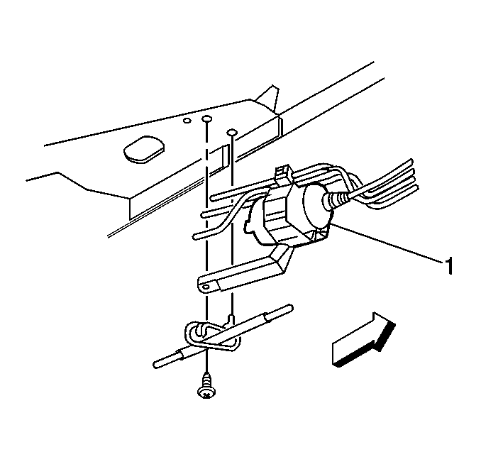
A steel in-line filter (1) is used in the fuel feed pipe ahead of the fuel injection system. The filter element is made of paper, and is designed to trap particles in the fuel that may damage the injection system. Quick-connect type fittings are used at both ends of the filter.
The PCM receives data from various information sensors, determines the required fuel and idle speed values and then controls the IAC valve, eight fuel injectors, and spark advance to maintain the optimum performance and driveability under all driving conditions. For more information on the PCM, refer to Powertrain Control Module Diagnosis .
The fuel pump relay allows the fuel pump to be energized by the PCM. When the ignition is first turned On, the PCM energizes the fuel pump relay for two seconds. This allows the fuel pump to run for two seconds and build up fuel pressure for cranking. The PCM then waits for ignition reference pulses from the Ignition Control Module (ICM). Once the PCM sees references pulses, the PCM energizes the relay to run the fuel pump.
A faulty fuel pump relay may cause long cranking times and should set a DTC.
