Removal Procedure
- Remove the IP assembly. Refer to Instrument Panel Assembly Replacement in Instrument Panel, Gages and Console.
- Disconnect the accelerator cable from the accelerator pedal assembly. Refer to Accelerator Control Cable Replacement in Engine Controls - 4.6L.
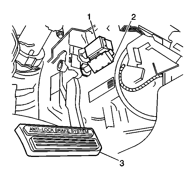
- Disconnect the electrical connectors from the stoplamp/ABS/shift lock switch (2).
- Disconnect the electrical connectors from the TCC/cruise control release switch (1).
- Remove the stop lamp/ABS/shift lock switch. Refer to Stop Lamp Switch Replacement .
- Remove the TCC/cruise control release switch. Refer to Torque Converter Clutch/Cruise Control Release Switch Replacement in Automatic Transaxle 4T80-E.
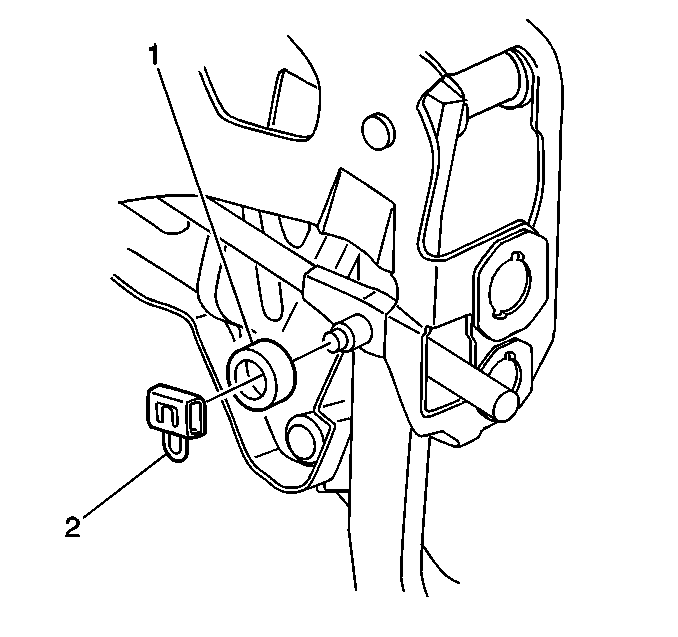
- Remove the vacuum brake booster pushrod retainer clip (2) from the brake pedal assembly clevis pin.
- Remove the foam spacer (1) from the brake pedal assembly clevis pin.
- Disconnect the vacuum brake booster push rod from the brake pedal assembly clevis pin.
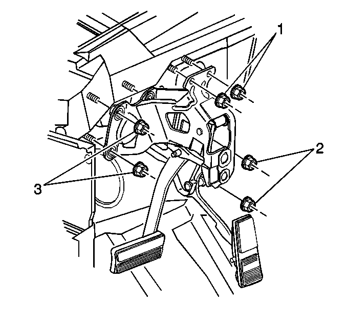
- Remove the brake pedal assembly mounting to cowl stud nuts (1).
- Remove the brake pedal assembly mounting nuts from the booster studs (2, 3).
- Remove the pedal assembly.


Installation Procedure
- Install the brake pedal assembly into position on the brake booster and cowl studs.
- Install the brake pedal assembly to brake booster mounting nuts.
- Install the brake pedal assembly to cowl stud mounting nuts (1).
- Apply a small amount of lubricant, GM P/N 12346293 or equivalent, to the clevis pin of the brake pedal.
- Connect the vacuum brake booster pushrod to the brake pedal assembly clevis pin.
- Install the foam spacer to the brake pedal assembly clevis pin.
- Install the retainer clip (2) to the brake pedal assembly clevis pin.
- Install the stop lamp/ABS/shift lock switch (2) to the brake pedal assembly. Refer to Stop Lamp Switch Replacement .
- Connect the electrical connector to the stoplamp/ABS/shift lock switch.
- Install the TCC/cruise control release switch (1) to the brake pedal assembly. Refer to Torque Converter Clutch/Cruise Control Release Switch Replacement in Automatic Transaxle 4T80-E.
- Connect the electrical connectors to the TCC/cruise control release switch (1).
- Connect the accelerator cable to the brake pedal assembly. Refer to Accelerator Control Cable Replacement in Engine Controls - 4.6L.
- Install the IP assembly. Refer to Instrument Panel Assembly Replacement in Instrument Panel, Gages and Console.

Notice: Use the correct fastener in the correct location. Replacement fasteners must be the correct part number for that application. Fasteners requiring replacement or fasteners requiring the use of thread locking compound or sealant are identified in the service procedure. Do not use paints, lubricants, or corrosion inhibitors on fasteners or fastener joint surfaces unless specified. These coatings affect fastener torque and joint clamping force and may damage the fastener. Use the correct tightening sequence and specifications when installing fasteners in order to avoid damage to parts and systems.
Tighten
Tighten the brake pedal assembly to booster stud mounting nuts to 36 N·m
(27 lb ft).
Tighten
Tighten the brake pedal assembly to cowl mounting nuts to 16 N·m
(12 lb ft).


