Removal Procedure
- Disable SIR. Refer to Disabling the SIR System in SIR.
- Remove the left knee bolster. Refer to Driver Knee Bolster Replacement .
- Remove the left knee bolster support. Refer to Driver Knee Bolster Bracket Replacement .
- Remove the right knee bolster. Refer to Passenger Knee Bolster Replacement .
- Remove the IP center seat or the floor console. Refer to Instrument Panel Compartment Replacement in Seats, or Front Floor Console Replacement .
- Remove the IP outer trim panels. Refer to Instrument Panel Outer Trim Cover Replacement - Right Side and Instrument Panel Outer Trim Cover Replacement - Left Side .
- Remove the windshield pillar trim. Refer to Windshield Pillar Garnish Molding Replacement in Interior Trim.
- Remove the defroster grille. Refer to Defroster Grille Replacement .
- Remove the IP upper trim pad. Refer to Instrument Panel Upper Trim Pad Replacement .
- Remove the heads up display, if equipped with UV8. Refer to Head Up Display Module Replacement .
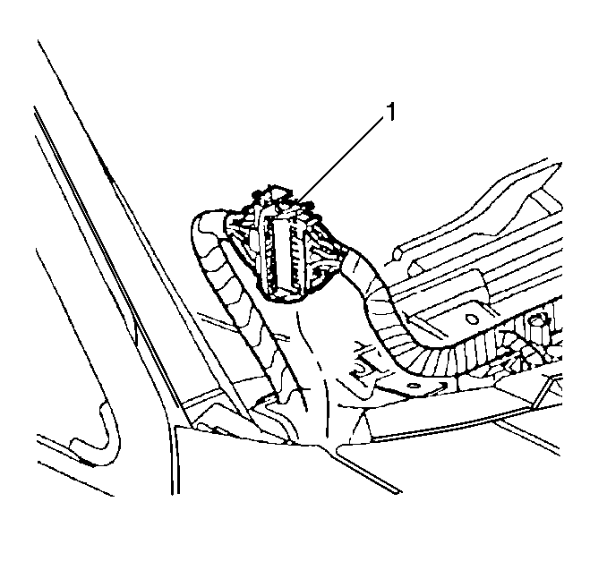
- Disconnect the body to IP electrical connectors (1) at the top, outside corners of IP.
- Disconnect all other electrical connectors from the IP to body.
- Disconnect the steering column shaft from the steering column.
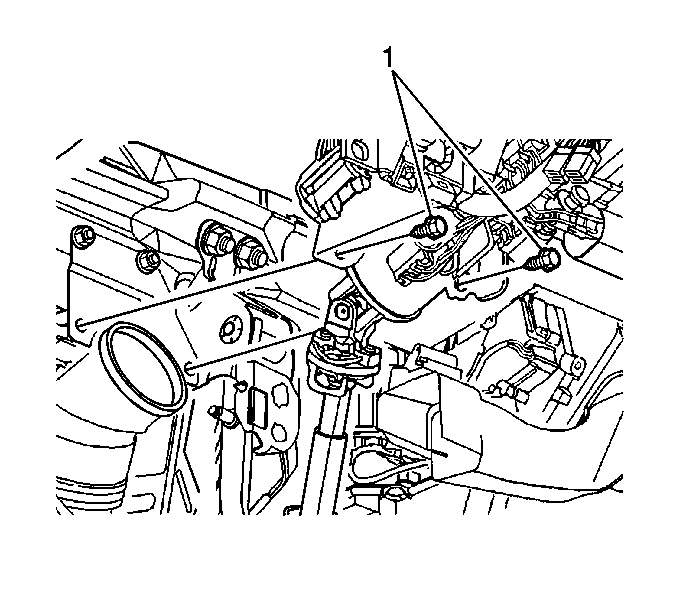
- Remove the steering column to body bolts (1). Refer to Steering Column Replacement in Steering Wheel and Column.
- For a DeVille base model, or the DeVille DHS, disconnect the shift cable from the steering column.
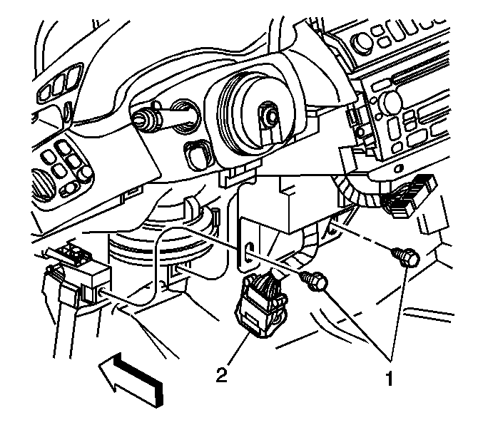
- Disconnect the Steering column to body connectors.
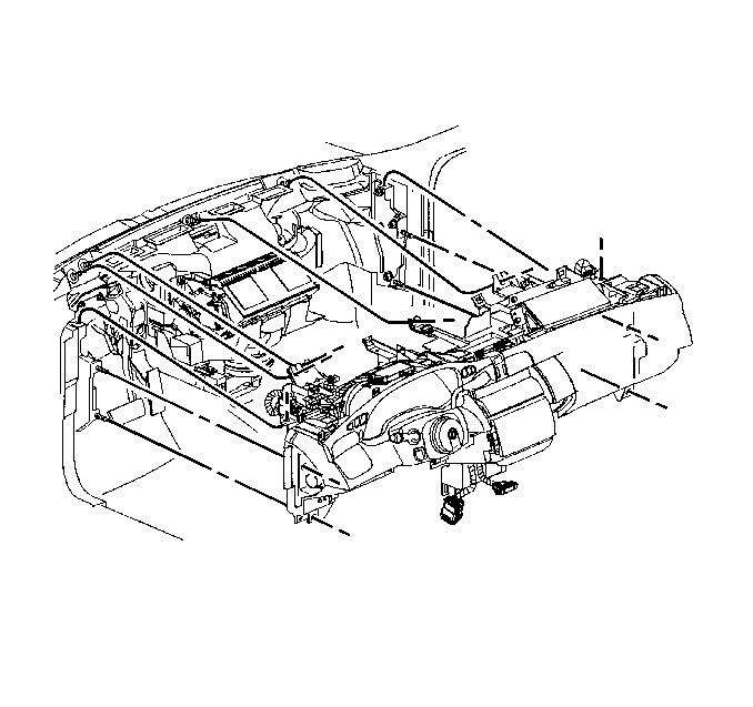
- Remove the IP center support bracket bolts (1) to floor bracket.
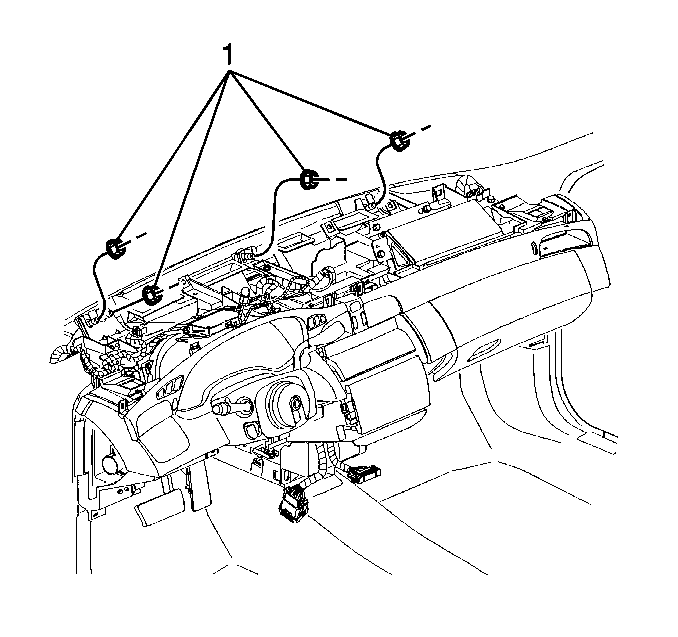
- Remove IP carrier (1) to cowl nuts.
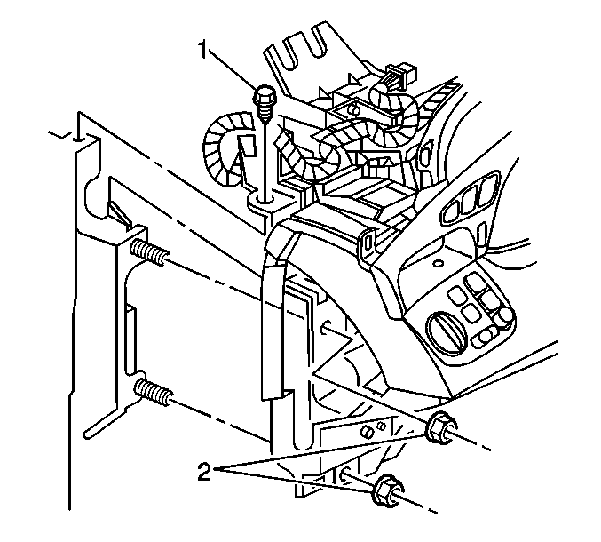
- Remove the bolt (1) and nuts (2) from the left and right IP carrier to hinge pillar.
- Remove the IP and carrier assembly from the vehicle.
Caution: Refer to SIR Caution in the Preface section.
Installation Procedure
- Install the IP and carrier assembly to the vehicle.
- Install the nuts and bolts (1, 2) to the IP carrier.
- Install the IP carrier to cowl nuts (1).
- Install the IP center support bracket bolts (1) to floor bracket.
- Install the steering column bolts (1). Refer to Steering Column Replacement in Steering Wheel and Column.
- For a DeVille base model, or the DeVille DHS, Install the shift cable to the steering column.
- Connect Steering column to body electrical connectors.
- Connect the IP to body electrical connectors (1) at top outside corners of IP.
- Install the heads up display, if equipped with UV8. Refer to Head Up Display Module Replacement .
- Install the IP upper trim pad. Refer to Instrument Panel Upper Trim Pad Replacement .
- Install the defroster grille. Refer to Defroster Grille Replacement .
- Install the windshield pillar trim. Refer to Windshield Pillar Garnish Molding Replacement in Interior Trim.
- Install the center seat or the center console. Refer to Instrument Panel Compartment Replacement in Seats, or Front Floor Console Replacement .
- Install the left and right IP outer trim panels. Refer to Instrument Panel Outer Trim Cover Replacement - Right Side and Instrument Panel Outer Trim Cover Replacement - Left Side .
- Install the left knee bolster support bracket. Refer to Driver Knee Bolster Bracket Replacement .
- Install the left knee bolster. Refer to Driver Knee Bolster Replacement .
- Install the right knee bolster. Refer to Passenger Knee Bolster Replacement .
- Enable the SIR. Refer to Enabling the SIR System in SIR.


Notice: Use the correct fastener in the correct location. Replacement fasteners must be the correct part number for that application. Fasteners requiring replacement or fasteners requiring the use of thread locking compound or sealant are identified in the service procedure. Do not use paints, lubricants, or corrosion inhibitors on fasteners or fastener joint surfaces unless specified. These coatings affect fastener torque and joint clamping force and may damage the fastener. Use the correct tightening sequence and specifications when installing fasteners in order to avoid damage to parts and systems.
Tighten
Tighten the IP carrier nuts and bolts to 25 N·m (18 lb ft).

Tighten
Tighten the IP carrier to cowl nuts to 25 N·m (18 lb ft).

Tighten
Tighten the IP center support bracket bolts to 25 N·m
(18 lb ft).


