For 1990-2009 cars only
Adjust Link Replacement FE1 and FE3
Tools Required
J 24319-B Steering Linkage Puller
Removal Procedure
- Raise and support the vehicle. Refer to Lifting and Jacking the Vehicle in General Information.
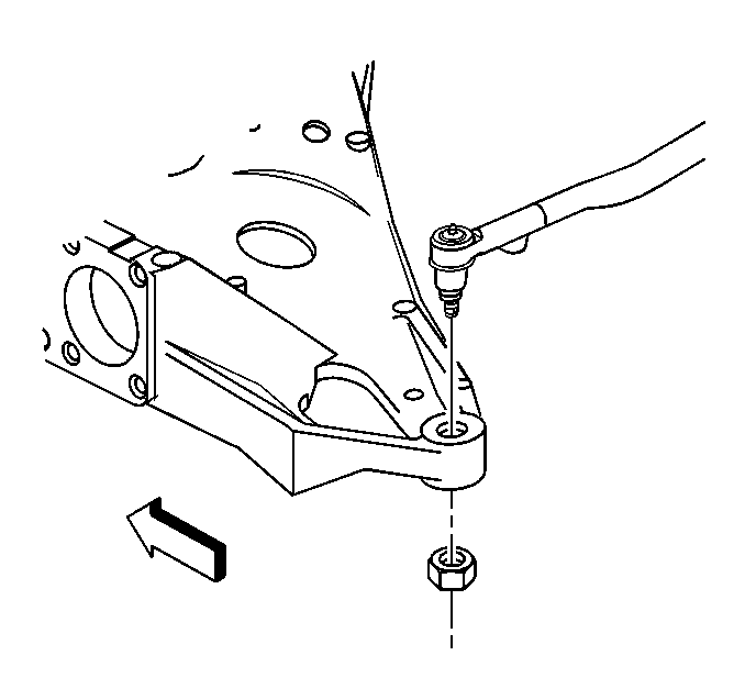
- Remove the hex nut from the adjustment link.
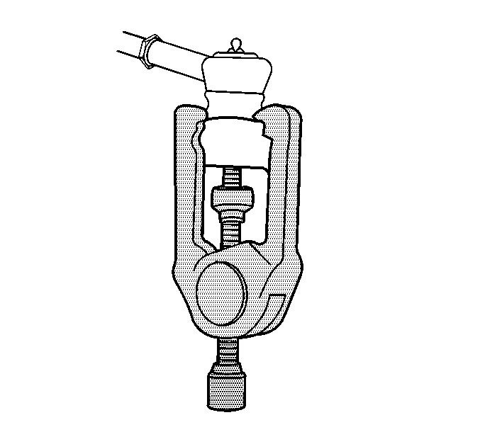
- Using the J 24319-B
- Using a block of wood and a suitable jack, support the rear support assembly.
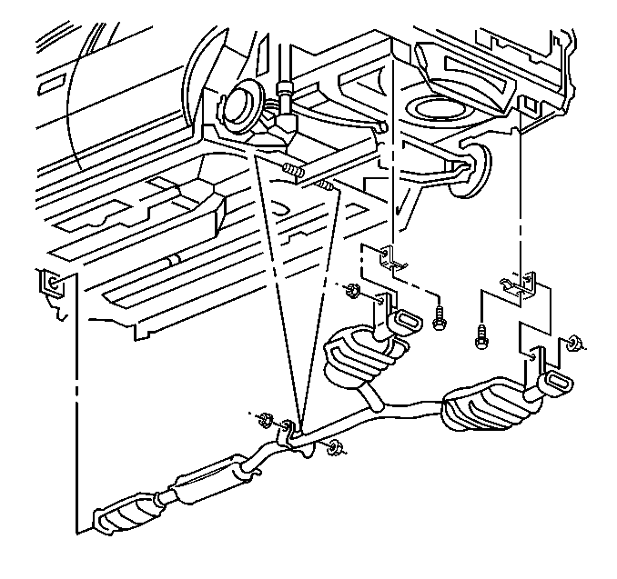
- Remove the exhaust. Refer to Exhaust System Replacement in Engine Exhaust.
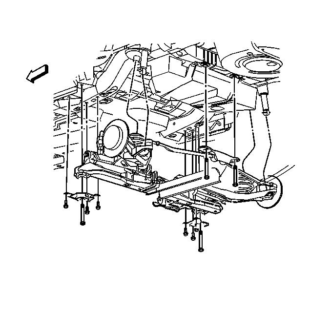
- Remove the two rear support assembly bolts and lower the support assembly.
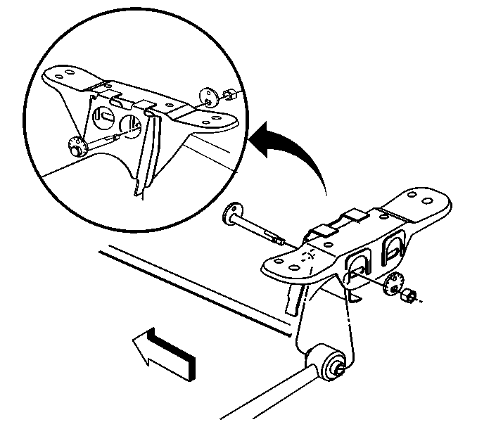
- Remove the cam lock nut and the bolt.
- Remove the adjustment link from the support assembly.
Installation Procedure
- Install the adjustment link to the support assembly.
- Install the cam lock nut, washer and bolt.
- Install the adjustment link to the control arm nut.
- Raise the support assembly.
- Install the rear two bolts in the support assembly to the body of the vehicle.
- Remove the exhaust. Refer to Exhaust System Replacement in Engine Exhaust.
- Lower the vehicle.
- Check the rear toe adjustment. Refer to Rear Toe Adjustment .

Notice: Refer to Fastener Notice in the Preface section.
Tighten
Tighten the cam lock nut to 91 N·m (67 lb ft).
Tighten
Tighten the nut to 30 N·m (22 lb ft) then tighten an additional 180 degrees.

Tighten
Tighten the support bolts to 191 N·m (141 lb ft).

Adjust Link Replacement FE7
Tools Required
J 24319-B Steering Linkage Puller
Removal Procedure
- Raise and support the vehicle. Refer to Lifting and Jacking the Vehicle .
- Remove the hex nut from the adjustment link.
- Using the J 24319-B separate the adjustment link from the lower control arm.
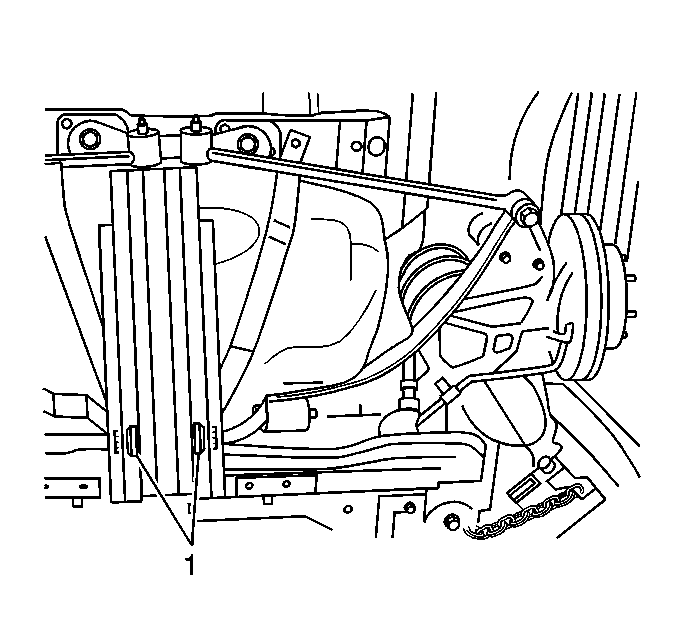
- Remove the support bracket bolts from the center support (1).
- Using a block of wood and suitable jack, support the rear support assembly.
- Remove the exhaust. Refer to Exhaust System Replacement .
- Remove two rear support assembly bolts and lower the support assembly.
- Remove the cam lock nut and the bolt.
- Remove the adjustment link from the support assembly.
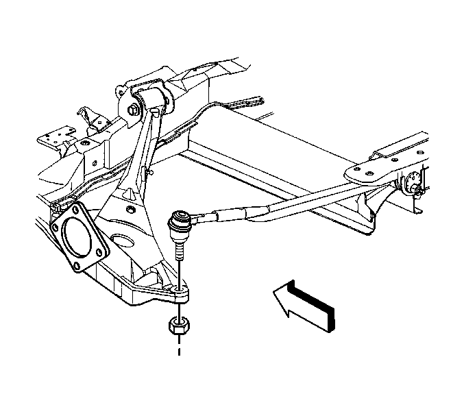
Important: Hold the adjustment link studs with the hex tool.



Installation Procedure
- Install the adjustment link to the support assembly.
- Install the cam lock nut, washer and bolt.
- Install the adjustment link to the control arm hex nut.
- Raise the support assembly and the exhaust.
- Install the rear two bolts in the support assembly to the body of the vehicle.
- Install the exhaust. Refer to Exhaust System Replacement .
- Install the center support bracket bolts (1).
- Lower the vehicle.
- Check the rear toe adjustment. Refer to Rear Toe Adjustment .

Notice: Refer to Fastener Notice in the Preface section.
Tighten
Tighten the cam lock nut to 105 N·m (77 lb ft).

Tighten
Tighten the hex nut to 30 N·m (22 lb ft) then an additional 200 degrees.

Tighten
Tighten the support bolts to 207 N·m (153 lb ft).


Tighten
Tighten the center support bracket bolts to 128 N·m (94 lb ft)
