Removal Procedure
The automatic adjustment park brake pedal assembly and the front park brake cable are serviced as a unit. The front park brake cable has no threads and is not adjustable.
- Ensure the park brake pedal is in the full returned position.
- Raise and suitably support the vehicle. Refer to Lifting and Jacking the Vehicle in General Information.
- Pull down on the front park brake cable.
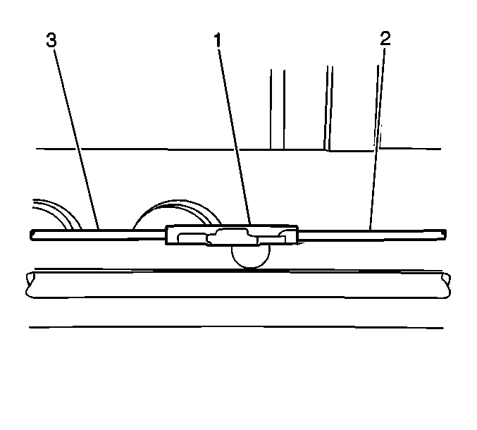
- Remove the cable (3) from the cable connector (1).
- Lower the vehicle.
- Remove the left closeout/insulator. Refer to Instrument Panel Insulator Panel Replacement - Left Side in Instrument Panel, Gages and Console.
- Remove the left knee bolster. Refer to Driver Knee Bolster Replacement in Instrument Panel, Gages and Console.
- Remove the left carpet retainer. Refer to Front Carpet Retainer Replacement in Interior Trim.
- Pull back the carpet.
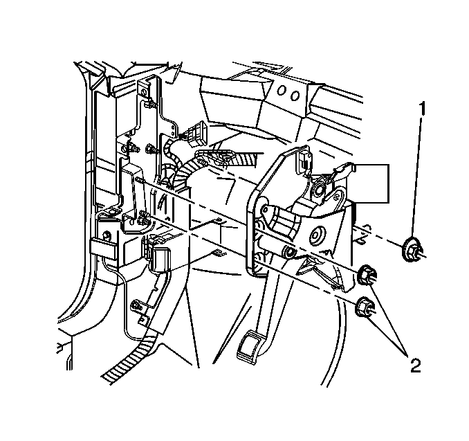
- Remove the park brake pedal assembly mounting nuts (1, 2).
- Position the park brake pedal assembly away from the mounting studs.
- Disconnect the electrical connector from the park brake warning light switch.
- Remove the park brake pedal assembly.


Installation Procedure
- Connect the electrical connectors to the park brake warning light switch.
- Install the park brake pedal assembly into the vehicle.
- Install the park brake pedal assembly mounting nuts (1, 2) to the vehicle.
- Raise the vehicle. Refer to Lifting and Jacking the Vehicle in General Information.
- Reconnect the front park brake cable (3) to the cable connector (1).
- Lower the vehicle.
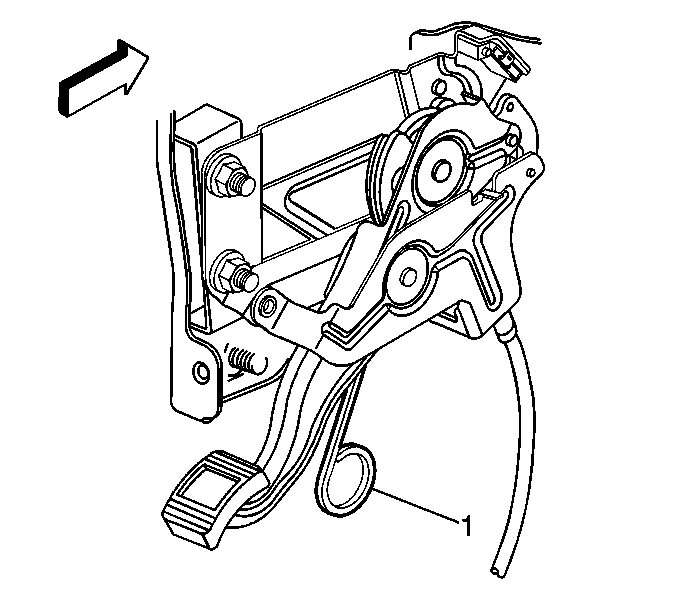
- If installing a new park brake pedal assembly, you must remove the park brake pedal and cable set pin (1).
- Install the left knee bolster. Refer to Driver Knee Bolster Replacement in Instrument Panel, Gages and Console.
- Install the left closeout/insulator. Refer to Instrument Panel Insulator Panel Replacement - Left Side in Instrument Panel, Gages and Console.
- Install the left carpet retainer. Refer to Front Carpet Retainer Replacement in Interior Trim.

Notice: Use the correct fastener in the correct location. Replacement fasteners must be the correct part number for that application. Fasteners requiring replacement or fasteners requiring the use of thread locking compound or sealant are identified in the service procedure. Do not use paints, lubricants, or corrosion inhibitors on fasteners or fastener joint surfaces unless specified. These coatings affect fastener torque and joint clamping force and may damage the fastener. Use the correct tightening sequence and specifications when installing fasteners in order to avoid damage to parts and systems.
Tighten
Tighten the park brake pedal assembly mounting nuts
to 24 N·m (18 lb ft).


| • | To set the park brake cable tension rotate the tension release pin (1) 80 degrees and then pull down to remove. |
| • | Apply the park brake pedal 3 full cycles to complete the tension set. |
