Removal Procedure
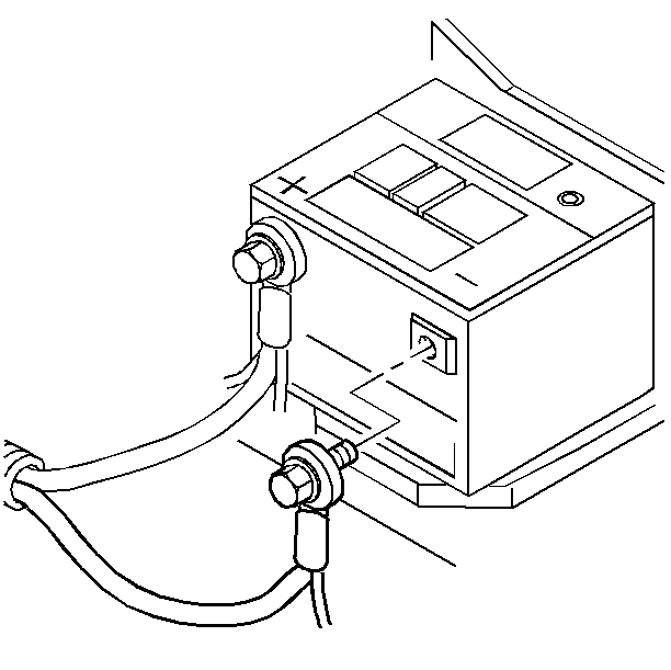
- Disconnect the battery negative cable
assembly from the battery negative terminal. Refer to
Caution: Unless directed otherwise, the ignition and start switch must be in the OFF or LOCK position, and all electrical loads must be OFF before servicing any electrical component. Disconnect the negative battery cable to prevent an electrical spark should a tool or equipment come in contact with an exposed electrical terminal. Failure to follow these precautions may result in personal injury and/or damage to the vehicle or its components.
in General Information. - Remove the bottom pan and seal, the scavenger screens, and the lip seals. Refer to Scavenge Screens and Seals Replacement .
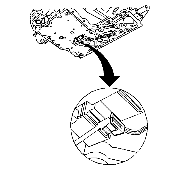
- Disconnect the transmission wire harness connectors from the pressure switch and the shift solenoids A and B. Use a small screwdriver.
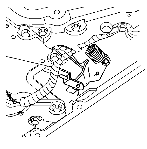
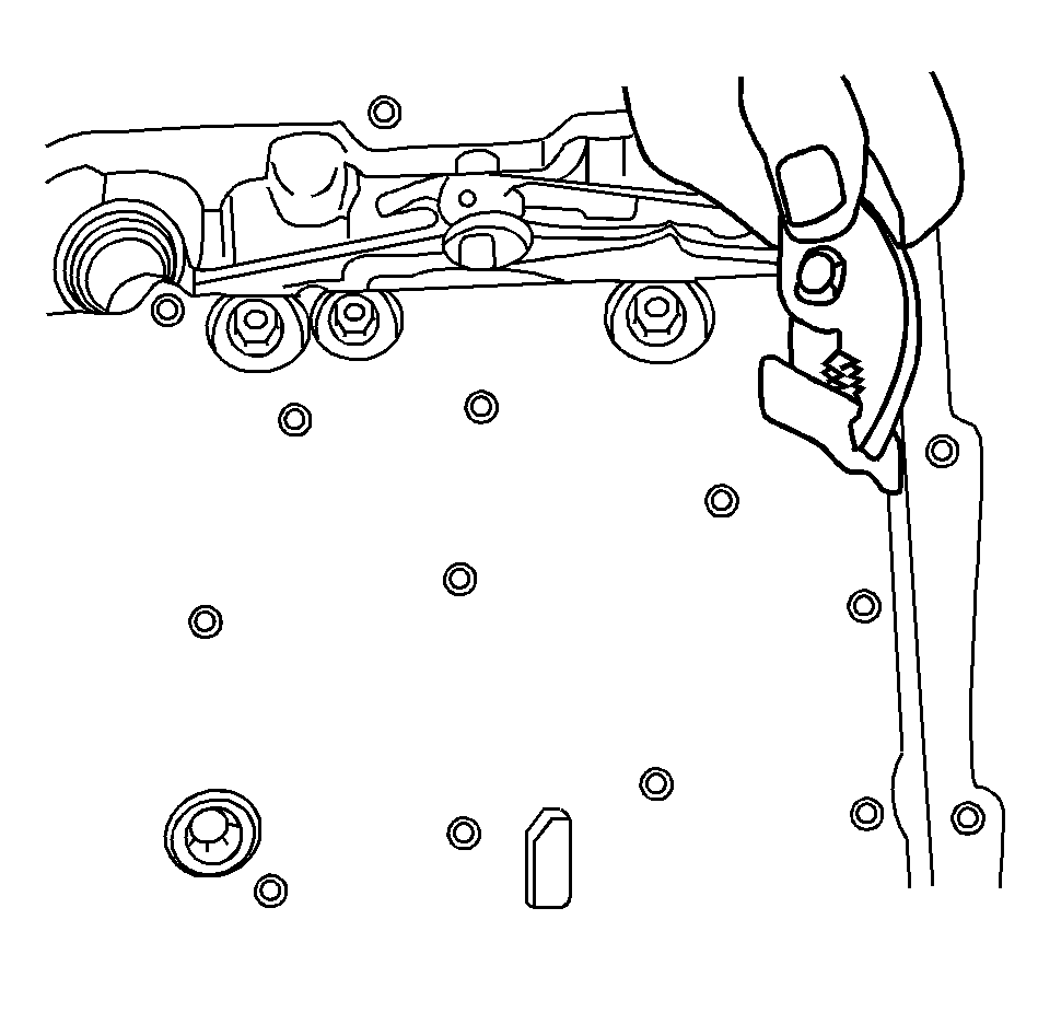
- Remove the manual valve linkage clip with a small screwdriver.
- Remove the wiring harness from the retaining clips on the lower controls assembly.
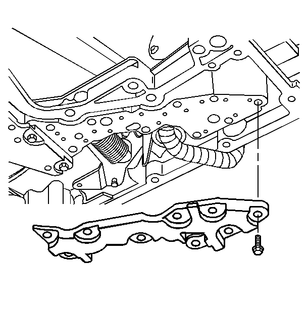
- Remove the oil transfer plate.
- Remove the bolts and the 2 nuts. Do not remove the 5 bolts shown on the lower channel plate.
- Remove the lower channel plate and the valve body and accumulator assembly from the case:
Installation Procedure
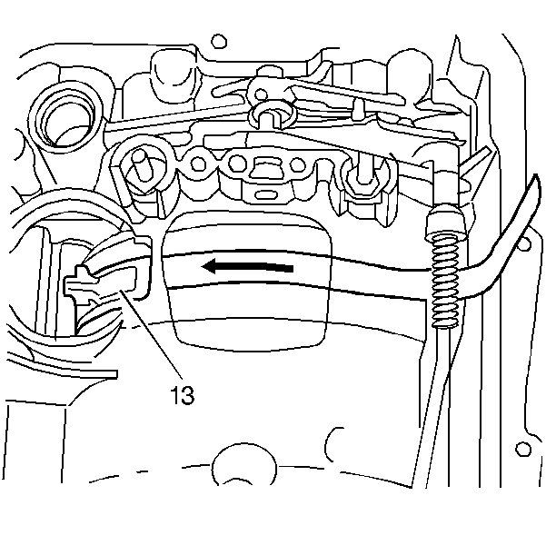
- Position the low reverse band, using a piece of shim stock (shim thickness 0.508--0.762 mm (020--0.030 in).
- Place the lower controls against the forward support studs.
- Hand-start the bolts into the channel plate. Bolts without a flange are next to the transfer plate.
- Remove the shim stock.
- Place the oil transfer plate over the open gasket area. Hand-start the bolts to hold the plate in place. Note the installation order of the alignment bolts.
- Install the 2 nuts on the forward support studs.
- Connect the manual valve to the detent lever. Route the harness over the spacer plate rib and the detent lever. Snap into the retaining clips on the lower controls assembly.
- Install the transmission wire harness connectors to the pressure switch and the shift solenoids A and B.
- Install the bottom pan and seal, the scavenger screens, and the lip seals. Refer to Scavenge Screens and Seals Replacement .
- Connect the battery negative cable assembly to the battery negative terminal.
- Add DEXRON-III transmission fluid as required. Refer to Automatic Transmission Fluid and Filter Replacement and to Fluid Capacity Specifications .
- If there was a complete fluid change, reset the transmission oil life indicator. Refer to Electronic Component Description .

Tighten
Tighten the bolts and nuts to 8 N·m (71 lb in).
Notice: Use the correct fastener in the correct location. Replacement fasteners must be the correct part number for that application. Fasteners requiring replacement or fasteners requiring the use of thread locking compound or sealant are identified in the service procedure. Do not use paints, lubricants, or corrosion inhibitors on fasteners or fastener joint surfaces unless specified. These coatings affect fastener torque and joint clamping force and may damage the fastener. Use the correct tightening sequence and specifications when installing fasteners in order to avoid damage to parts and systems.


Tighten
Tighten the terminal bolt to 15 N·m (11 lb ft).
