Removal Procedure
- Remove the rear seat back. Refer to Rear Seat Back Replacement in Seats.
- Remove the rear compartment front trim panel. Refer to Rear Compartment Front Trim Panel Replacement .
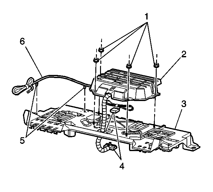
- Remove the 4 fasteners (1) from the OnStar® module bracket assembly (2).
- Disengage the retainers (5) securing the coaxial cable (6) to the seat back panel.
- Lower the module bracket assembly into the rear compartment.
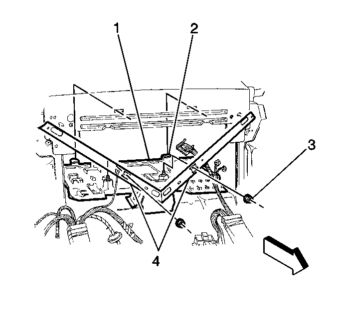
- Remove the 2 nuts (3) from the lower section of the seat back panel (1).
- Lift upward in order to disengage the upper tabs from the pass-through panel.
- Carefully lay the electrical component mounting bracket (1) into the rear compartment.
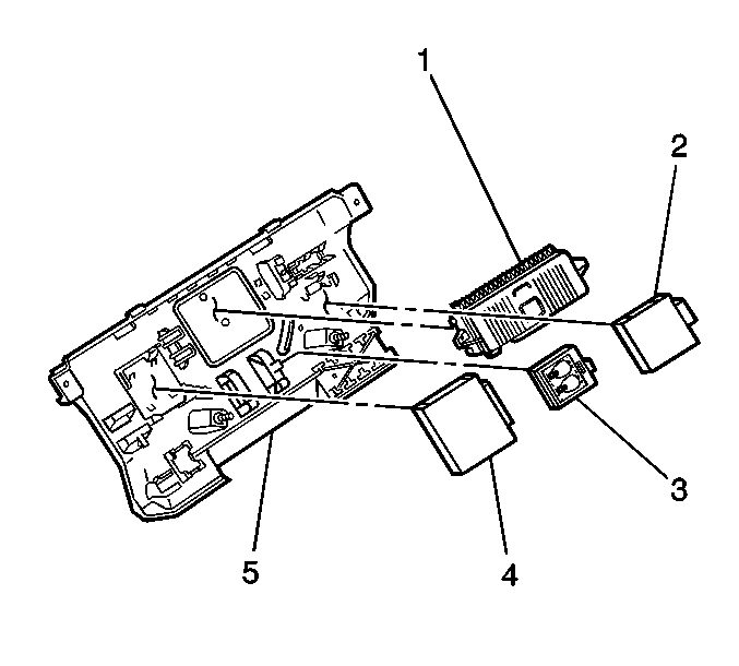
- Remove the following modules:
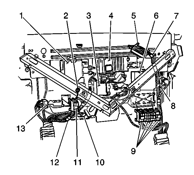
- Remove the following relay centers and fuse blocks:
- Disconnect the electrical ground (2)
- Remove and transfer the pass-through rubber grommet (10)
- Remove the electrical component mounting bracket from the rear compartment.


| • | Radio Amplifier/Radio Interface Module RIM (1) |
| • | Body Control Module PZM (2) |
| • | Door Lock Module RFA (3) |
| • | Continuously Variable Road Sensing Suspension Module CVRSS (4) |

| • | Rear Fuse Block (5) |
| • | Rear Compartment Relay Center 1, 2, 3 (9) |
| • | Rear Compartment Relay Center 4 (11) |
| • | Power Door Lock Relay (13) |
Installation Procedure
- Place the electrical component mounting bracket into the rear compartment.
- Install the following relay centers and fuse blocks:
- Install the following modules:
- Lift the electrical component mounting bracket and secure the locating tabs on the mounting bracket to the slots in the pass through panel.
- Ensure the tabs on the mounting bracket are secure to the pass through panel brace.
- Install the fasteners (3) in order to secure the electrical component mounting bracket.
- Connect the electrical ground.
- Secure the ground fasteners.
- Install the OnStar® module bracket assembly (2) to the seat back panel.
- Install the 4 fasteners (1) to the OnStar® module bracket assembly (2).
- Engage the retainers (5) securing the coaxial cable (6) to the seat back panel.
- Install the rear compartment front trim panel. Refer to Rear Compartment Front Trim Panel Replacement .
- Install the rear seat back. Refer to Rear Seat Back Replacement in Seats.
- Perform the OnStar® reconfiguration procedure. Refer to OnStar Reconfiguration in Cellular Communications.

| • | Rear Fuse Block (5) |
| • | Rear Compartment Relay Center 1, 2, 3 (9) |
| • | Rear Compartment Relay Center 4 (11) |
| • | Power Door Lock Relay (13) |

| • | Radio Amplifier/Radio Interface Module RIM (1) |
| • | Body Control Module PZM (2) |
| • | Door Lock Module RFA (3) |
| • | Continuously Variable Road Sensing Suspension Module CVRSS (4) |

Notice: Use the correct fastener in the correct location. Replacement fasteners must be the correct part number for that application. Fasteners requiring replacement or fasteners requiring the use of thread locking compound or sealant are identified in the service procedure. Do not use paints, lubricants, or corrosion inhibitors on fasteners or fastener joint surfaces unless specified. These coatings affect fastener torque and joint clamping force and may damage the fastener. Use the correct tightening sequence and specifications when installing fasteners in order to avoid damage to parts and systems.
Tighten
Tighten the fasteners to 10 N·m (89 lb in).
Tighten
Tighten fasteners to 10 N·m (89 lb in).

Tighten
Tighten the 4 fasteners to 9 N·m (80 lb in).
