For 1990-2009 cars only
Fuel Injection Fuel Rail Assembly Replacement - Bank 1 LLT
Removal Procedure
- Relieve the fuel system pressure. Refer to Fuel Pressure Relief.
- Remove the cross vehicle brace. Refer to Cross Vehicle Brace Replacement.
- Remove the fuel pipe shield. Refer to Fuel Pipe Shield Replacement.
- Remove the intake manifold. Refer to Intake Manifold Replacement.
- Remove the high pressure fuel pipe. Discard the pipe. Refer to Fuel Feed Intermediate Pipe Replacement.
- Remove the fuel rail crossover pipe. Refer to Fuel Injection Fuel Rail Crossover Tube Replacement. Discard the pipe.
- Remove the foam insulator from the fuel rails.
- Disconnect the fuel pressure sensor electrical connector and cut the wire harness tie straps.
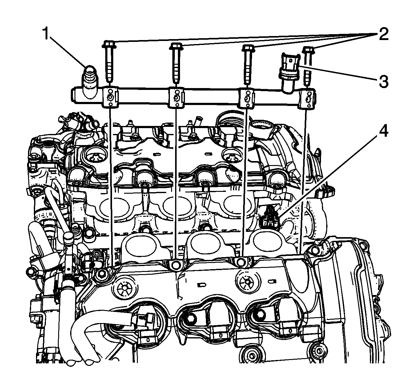
- Remove the fuel rail (1) bolts (2).
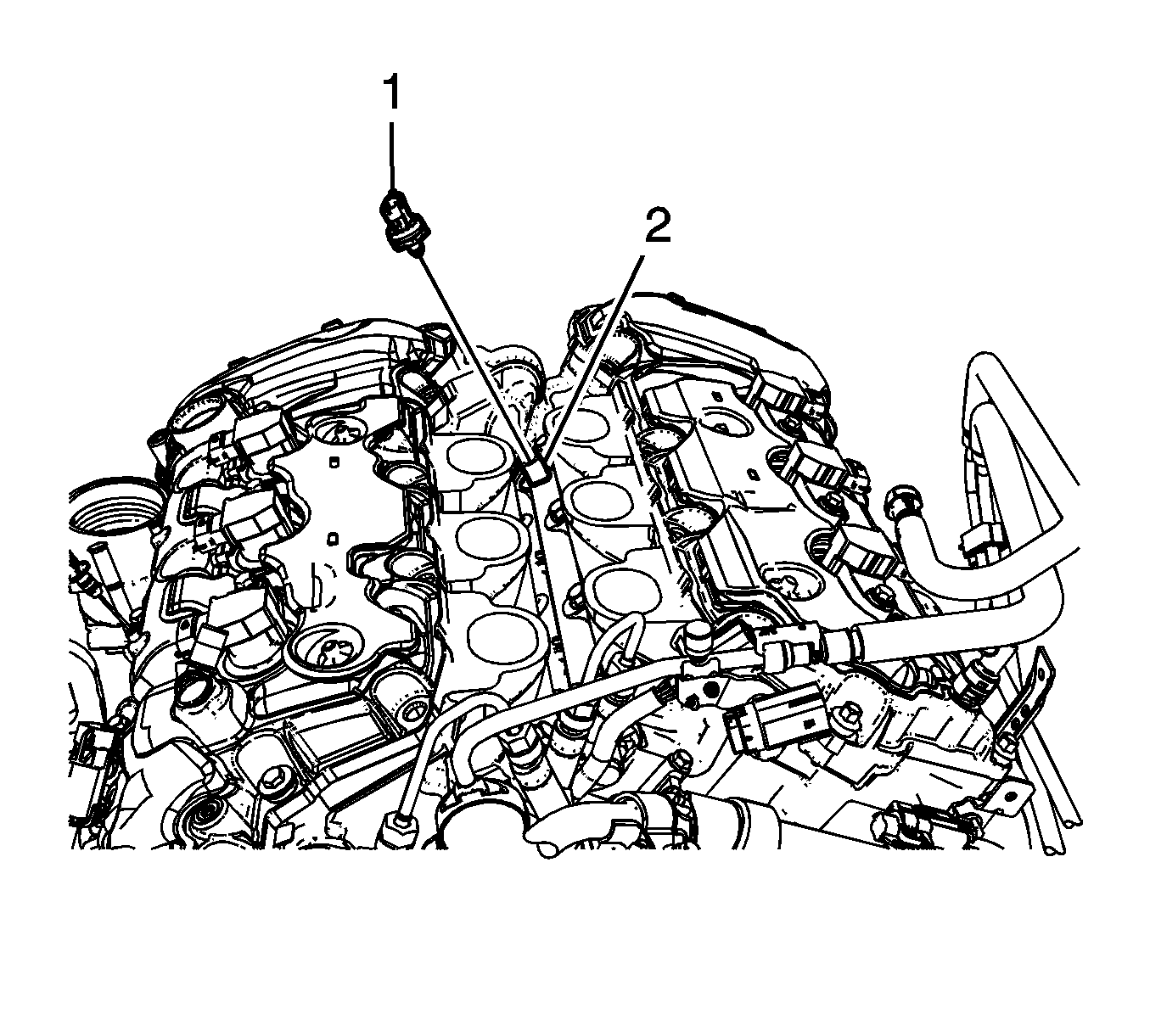
- Remove the fuel pressure sensor. Refer to Fuel Pressure Sensor Replacement.
- Remove and discard the direct fuel injector hold down clamps.
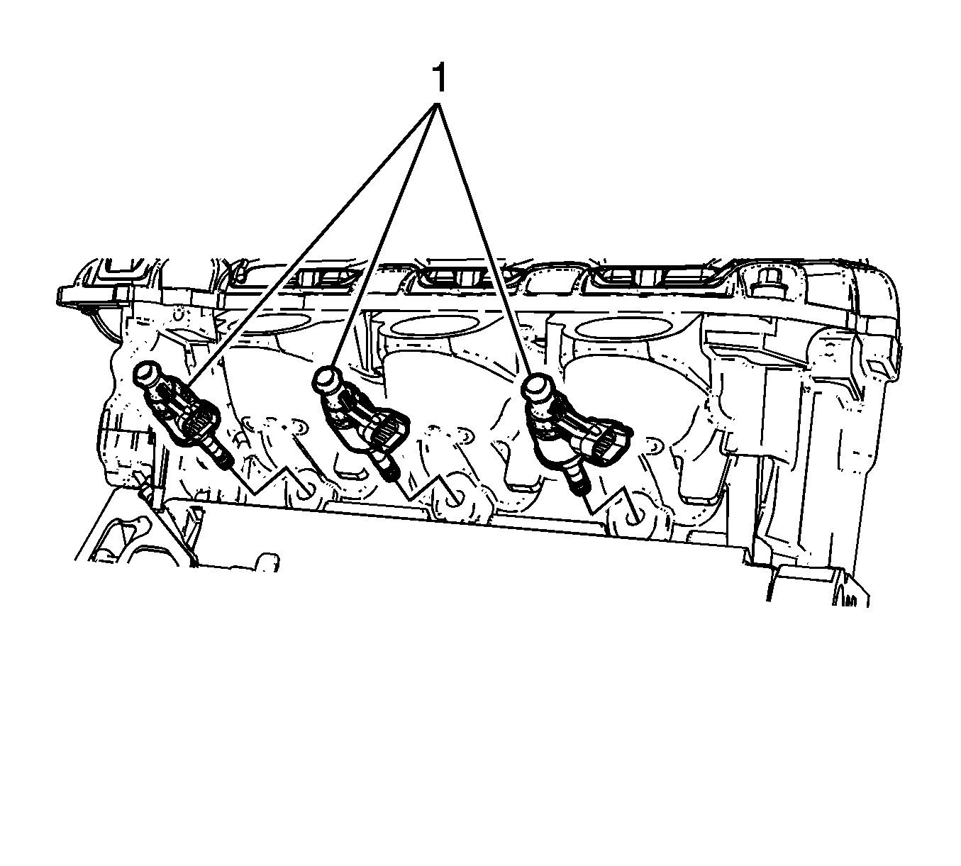
- Once the fuel rail is removed, remove the fuel injectors and rebuild them. Refer to Fuel Injector Replacement.


Caution: Note the correct routing of the electrical wiring. Failure to reinstall the wiring properly could result in damage to the wiring.
Note: The direct fuel injectors must be rebuilt whenever the injector has been released from the fuel rail or cylinder head.
Installation Procedure
- Install the rebuilt direct fuel injectors (1) to the cylinder heads. Refer to Fuel Injector Replacement.
- Install NEW direct injector hold down clamps to the injector.
- On a new fuel rail, lubricate the fuel injector cups with silicon free engine oil GM P/N 12345610 (Canadian P/N 9931930) or equivalent.
- Carefully place the fuel rail (1) into position, placing the front into the fuel rail over the front injector and rotating the rear downward.
- Install the 2 outer fuel rail bolts first, then the 2 inner bolts, and hand tighten.
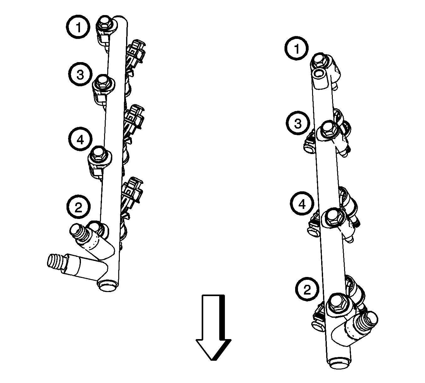
- Tighten the fuel rail bolts in the sequence shown:
- Tighten the Bank 1 fuel rail bolts first pass to 12 N·m (106 lb in).
- Tighten the Bank 1 fuel rail bolts final pass to 23 N·m (17 lb ft).
- Install a NEW fuel rail crossover pipe. Refer to Fuel Injection Fuel Rail Crossover Tube Replacement.
- Install a NEW high pressure fuel pipe. Refer to Fuel Feed Intermediate Pipe Replacement.
- Install the high pressure fuel sensor (1). Refer to Fuel Pressure Sensor Replacement.
- Connect the fuel injector wiring harness electrical connector (1) to the fuel injectors, fuel rail and fuel pressure sensor.
- Inspect for fuel leaks using the following procedure:
- Install the foam insulator from the fuel rails.
- Install the intake manifold. Refer to Intake Manifold Replacement.
- Install the fuel pipe shield. Refer to Fuel Pipe Shield Replacement.
- Install the low side fuel pressure service port cap.
- Install the fuel tank cap.
- Install the cross vehicle brace. Refer to Cross Vehicle Brace Replacement.


Caution: Refer to Fastener Caution in the Preface section.

Tighten

| 11.1. | Turn ON the ignition, with the engine OFF for 2 seconds. |
| 11.2. | Turn OFF the ignition, for 10 seconds. |
| 11.3. | Turn ON the ignition, with the engine OFF. |
| 11.4. | Inspect for fuel leaks. |
