For 1990-2009 cars only
Removal Procedure
- Disconnect the negative battery cable. Refer to Battery Negative Cable Disconnection and Connection.
- Remove the engine sight shield. Refer to Intake Manifold Sight Shield Replacement.
- Remove the front and rear sections of the supercharger inlet duct. Refer to Supercharger Inlet Duct Assembly Replacement.
- Position the charge air cooler fill port aside.
- Relieve the fuel system pressure. Refer to Fuel Pressure Relief.
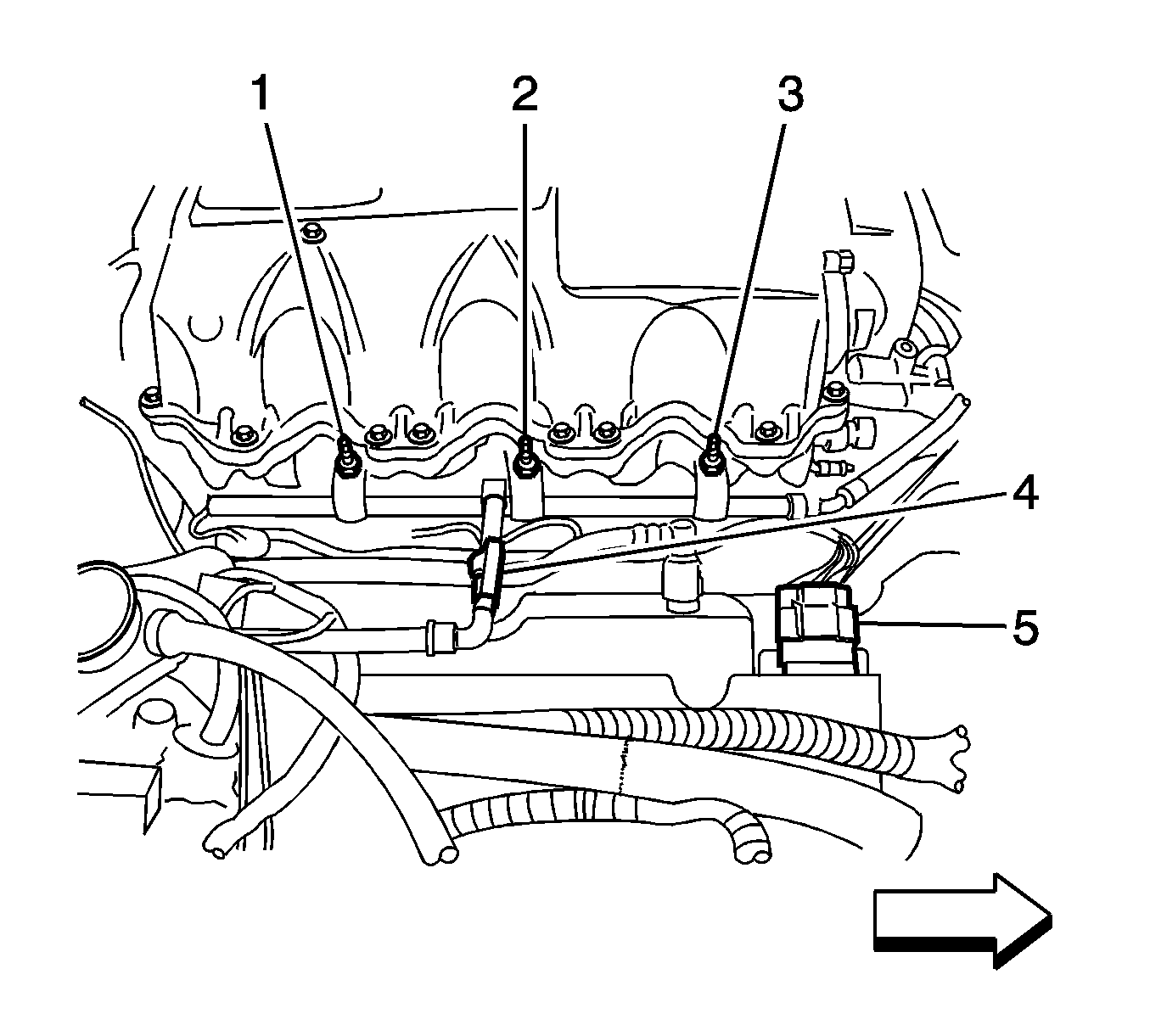
- Disconnect the fuel line (4) from the fuel rail. Position the line aside. Refer to Fuel Hose/Pipes Replacement - Engine Compartment.
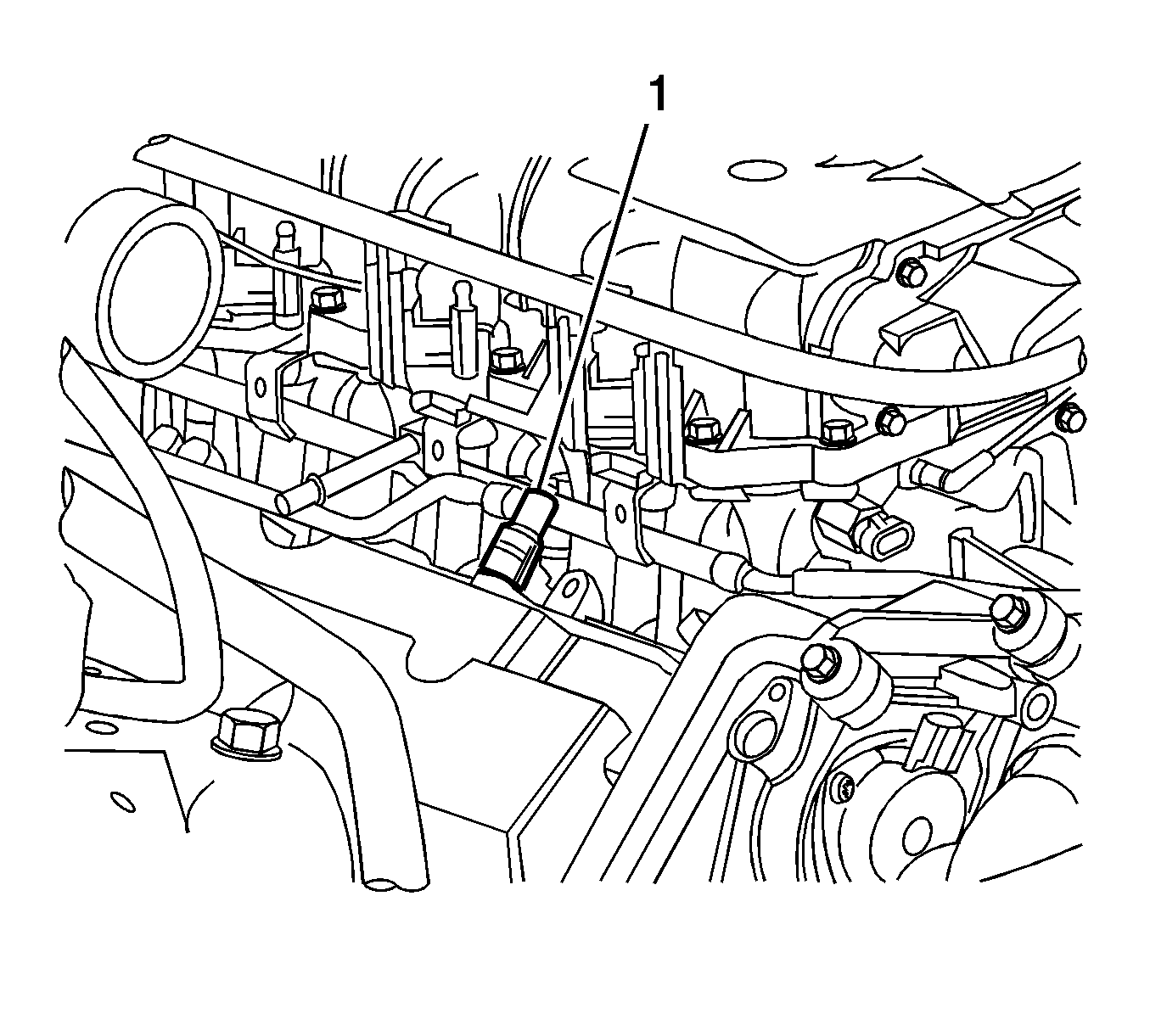
- Remove the positive crankcase ventilation (PCV) tube (1) from the right camshaft cover. Position the tube aside. Refer to Positive Crankcase Ventilation Hose/Pipe/Tube Replacement.
- Remove the battery and battery tray. Refer to Battery Tray Replacement.
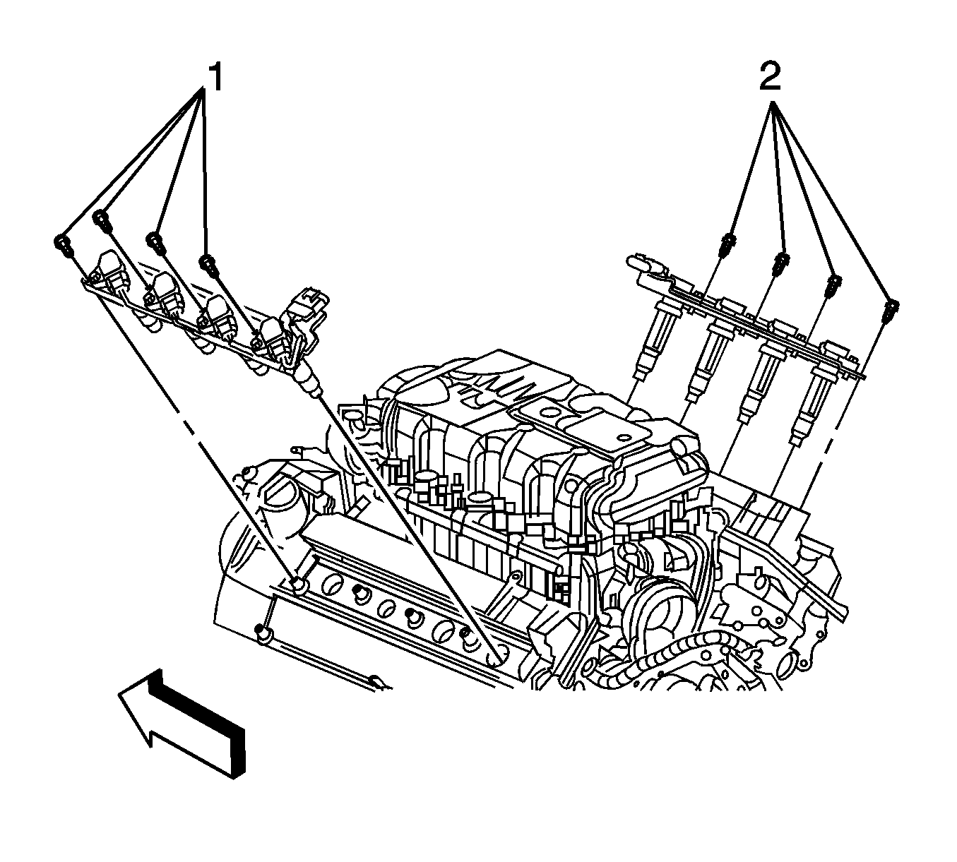
- Remove the right side ignition coils (2) as an assembly. Refer to Ignition Coil Replacement - Bank 1.
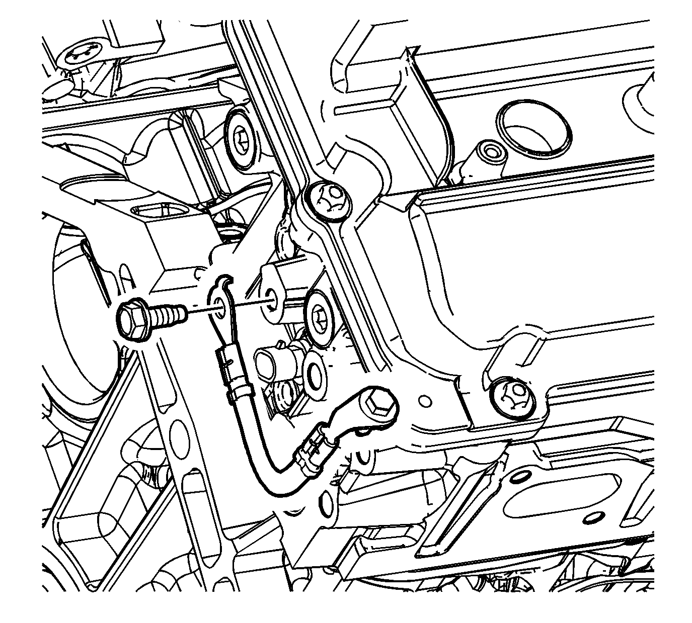
- Remove the bolt connecting the ground strap to the right camshaft cover.
- Remove the wiring harness clips from the camshaft cover.
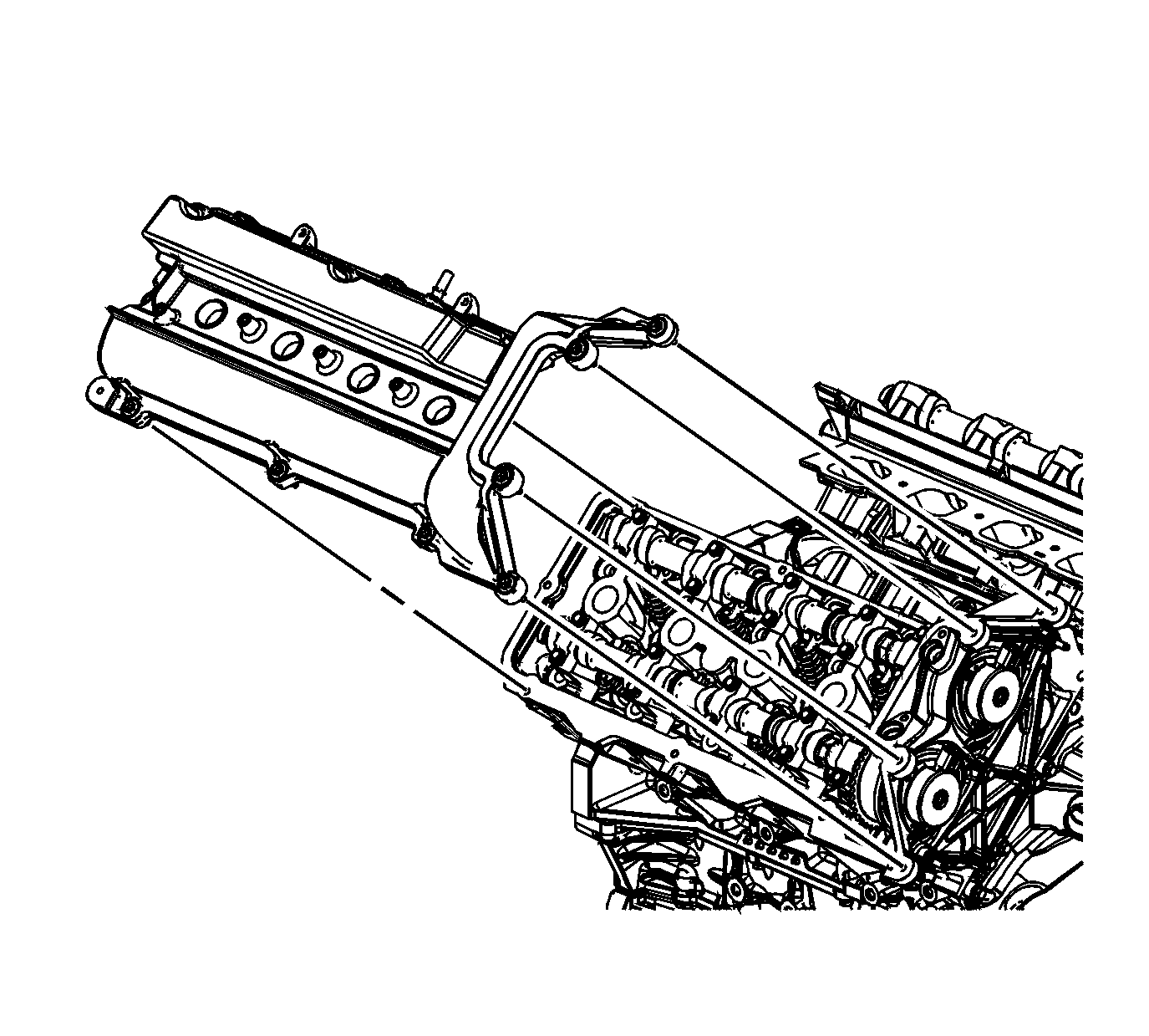
- Remove the camshaft cover bolts.
- Lift the camshaft drive end of the camshaft cover up.
- Remove the camshaft cover.
- Discard the camshaft cover gasket and spark plug port seals if there is any evidence of damage or if the seal comes out of the groove in the cover during removal.
- Clean the gasket mating surface on the cylinder head.
- Disassemble the camshaft cover if necessary. Refer to Camshaft Cover Disassemble.
- Clean and inspect the camshaft cover. Refer to Camshaft Cover Cleaning and Inspection.
Installation Procedure
- Install a new camshaft cover gasket to the camshaft cover, if necessary.
- Assemble the camshaft cover. Refer to Camshaft Cover Assemble.
- Place a small amount of sealant at the split line (1, 2) of the right cylinder head and the right camshaft position actuator housing. Refer to Adhesives, Fluids, Lubricants, and Sealers for the correct part number.
- Work the camshaft cover into position by pivoting the cover down and aligning the bolt holes.
- Install the camshaft cover bolts and tighten to 10 N·m (89 lb in).
- Install the wiring harness clips to the camshaft cover.
- Install the bolt connecting ground strap to the right camshaft cover and tighten to 10 N·m (89 lb in).
- Install the ignition coils (2) as an assembly. Refer to Ignition Coil Replacement - Bank 1.
- Install the battery tray and battery. Refer to Battery Tray Replacement.
- Install the positive crankcase ventilation (PCV) fresh air tube (1) to the right camshaft cover. Refer to Positive Crankcase Ventilation Hose/Pipe/Tube Replacement.
- Connect the fuel line (4) to the fuel rail. Refer to Fuel Hose/Pipes Replacement - Engine Compartment.
- Install the front and rear sections of the supercharger inlet duct. Refer to Supercharger Inlet Duct Assembly Replacement.
- Connect the negative battery cable. Refer to Battery Negative Cable Disconnection and Connection.
- Install the engine sight shield, cross car brace, and engine compartment sight shields. Refer to Intake Manifold Sight Shield Replacement.
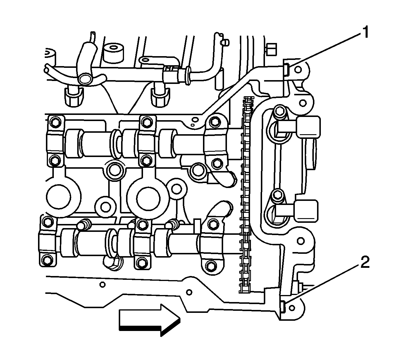
Note: Be careful to prevent the exposed section of the camshaft cover gasket from being damaged by the edge of the cylinder head casting.
Caution: Refer to Fastener Caution in the Preface section.


