Removal Procedure
Tools Required
| • | J 8062 Valve Spring Compressor |
| • | J 38821 Valve Spring Compressor Adapter |
| • | J 38819 Valve Keeper Remover/Installer |
| • | J 38820 Valve Stem Seal Remover/Installer |
- Remove the cylinder head. Refer to Cylinder Head Replacement .
- Remove the valve lifters and arrange them so they may be installed in their original position. Store lifters with the cam face down to prevent draining oil from the lifter.
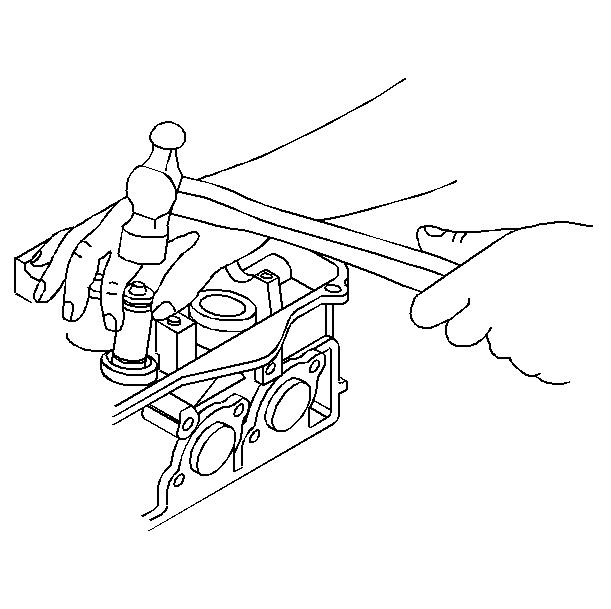
- Using an appropriately sized deep socket and a plastic hammer, lightly tap on the valve spring retainer to loosen the valve keepers.
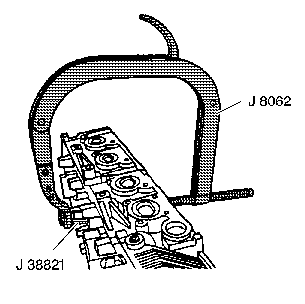
- Using valve spring compressor J 8062 and adapter J 38821 , compress the valve spring. Using the magnetic end of keeper remover / installer J 38819 , remove valve keepers.
- Remove the valve.
- Install J 38821 sleeve into lifter bore to protect the surface.
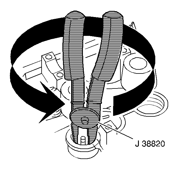
- Use the J 38820 in order to remove the valve stem seal by exerting a twist / pull motion with the tool. Discard the stem seal / spring seat.
- Inspect the following components. Refer to Valve Spring Inspection and Measurement .
Important: If the camshafts remain in the cylinder head some valves will always be held open. Do not set the cylinder head on a workbench with the cylinder face down. Damage to the valves will result.


| • | Valve |
| • | Valve seat |
| • | Valve stem-to-guide clearance |
| • | Valve spring |
Installation Procedure
- Use the J 38820 in order to install a new valve stem/spring seat by applying a twisting, pushing motion. The J 38820 should be in place for this operation.
- Coat the valve stem seal inner diameter with the engine oil.
- Lubricate the valve stem with engine oil and install the valve.
- Position the valve spring and retainer and using J 8062 and adapter J 38821 compress the valve spring.
- Install the valve keepers. Use the J 38819 and put the keeper into position by pushing the tool downward.
- Release the tension on the spring compressor and remove the J 38821 . Verify the valve keepers are in the installed position.
- Install the valve lifters into their original position.
- Lubricate the camshaft bearing journals with engine oil, and position the intake and exhaust camshafts to the cylinder head.
- Install the camshaft bearing caps into their original positions with the arrows pointing towards the front of the engine. Finger start all camshaft bearing cap bolts.
- Alternately tighten each pair of bearing cap bolts one turn at a time until the caps are snug with the cylinder head.
- Install the cylinder head. Refer to Cylinder Head Replacement


Tighten
Tighten the bolts to 12 N·m (106 lb in).
Notice: Use the correct fastener in the correct location. Replacement fasteners must be the correct part number for that application. Fasteners requiring replacement or fasteners requiring the use of thread locking compound or sealant are identified in the service procedure. Do not use paints, lubricants, or corrosion inhibitors on fasteners or fastener joint surfaces unless specified. These coatings affect fastener torque and joint clamping force and may damage the fastener. Use the correct tightening sequence and specifications when installing fasteners in order to avoid damage to parts and systems.
