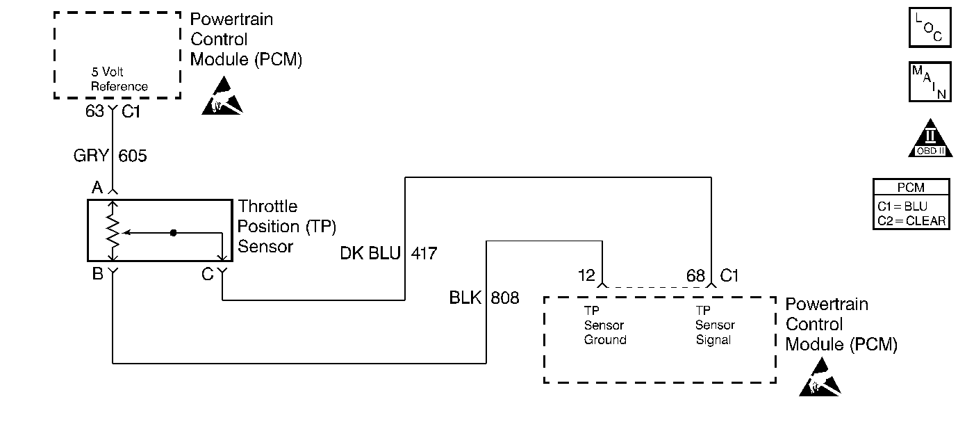
Circuit Description
The Throttle Position sensor is potentiometer. A 5 volt reference is provided on CKT 605 and ground is provided on CKT 808. The TP sensor signal CKT 417 varies between ground and 5 volts based on the position of the throttle plates. At low throttle angle, the TP sensor signal voltage is low. The PCM uses TP sensor information to determine idle, Wide Open Throttle (WOT), deceleration enleanment and acceleration enrichment. This diagnostic test monitors both the Manifold Absolute Pressure (MAP) and Throttle Position (TP) sensors. Engine operation requires that any large change in throttle position (TP) sensor must be followed by a change in manifold pressure (MAP). If the MAP remains constant following a large change in throttle angle, PCM DTC P0120 will set.
Conditions for Running the DTC
| • | DTCs P0107, and P0108 not set. |
| • | MAP greater than 21.8 kPa. |
| • | MAP not within 12 kPa of atmospheric pressure (BARO). |
| • | Engine speed at least 500 RPM. |
| • | Engine metal overtemp not active. |
| • | Traction control not active. |
Conditions for Setting the DTCs
MAP signal changes 3 kPa or less in .21 seconds following a 5 degree or greater INCREASE in throttle angle.
OR
MAP signal changes 2.2 kPa or less in .21 seconds following a 4.7 degree or greater DECREASE in throttle angle.
Action Taken When the DTC Sets
| • | The Malfunction Indicator Lamp (MIL) will not illuminate. |
| • | No message will be displayed. |
Conditions for Clearing the DTC
| • | A History DTC will clear after forty consecutive warm-up cycles with no failures of any non-emission related diagnostic test. |
| • | A Last Test Failed (current) DTC will clear when the diagnostic runs and does not fail. |
| • | Use a scan tool to clear DTCs. |
| • | Interrupting PCM battery voltage may or may not clear DTCs. This practice is not recommended. Refer to Clearing Diagnostic Trouble Codes in PCM Description and Operation. |
Diagnostic Aids
Use the scan tool snapshot and graph function to aid in diagnosing sensor performance failures. Refer to scan tool users guide for further information.
Test Description
Number(s) below refer to the step number(s) on the Diagnostic Table.
-
Since a misfire can cause DTC P0120 to set, if a misfire has occurred, it should be diagnosed first.
-
Checking DTC P0120 snapshot value to determine if an intermittent low voltage caused the DTC to set.
-
An intermittent low voltage can be caused by an open or short to ground on the TP sensor circuit or by an open in the TP sensor 5volt reference circuit or the TP sensor itself.
-
Checking the TP sensors ability to react to a known throttle angle.
-
Checking DTC P0120 snapshot value to determine if an intermittent high voltage caused the DTC to set.
-
An intermittent high voltage can be caused by an open in the TP sensor ground circuit or a short to voltage on the TP sensor signal circuit.
Step | Action | Value(s) | Yes | No | ||||
|---|---|---|---|---|---|---|---|---|
1 | Did you perform the Powertrain On-Board Diagnostic (OBD) System Check? | -- | ||||||
Is DTC P0300 also set? | -- | |||||||
3 | Are DTCs P0121 or P0122 set? | -- | Go to DTCs that are set | |||||
Select Failure Rec. and view TP sensor display. Is snapshot TP sensor reading less than the value specified? | 0 degrees | |||||||
Was an open or shorted condition repaired? | -- | Go to Powertrain Control Module Diagnosis for Verify Repair | ||||||
Was a skip or jump in TP sensor reading noted? | -- | Fault not present. | ||||||
7 |
Was a repair made? | -- | Go to Powertrain Control Module Diagnosis for Verify Repair | |||||
Is snapshot TP sensor reading greater than the value specified? | 85 degrees | |||||||
Was an open or shorted condition repaired? | -- | Go to Powertrain Control Module Diagnosis for Verify Repair | ||||||
10 |
Was a skip or jump in TP sensor reading noted? | -- | Fault not present. Refer to Diagnostic Aids | |||||
11 | Replace the Throttle Position sensor. Refer to Throttle Position Sensor Replacement . Is the replacement complete? | -- | Go to Powertrain Control Module Diagnosis for Verify Repair | -- |
