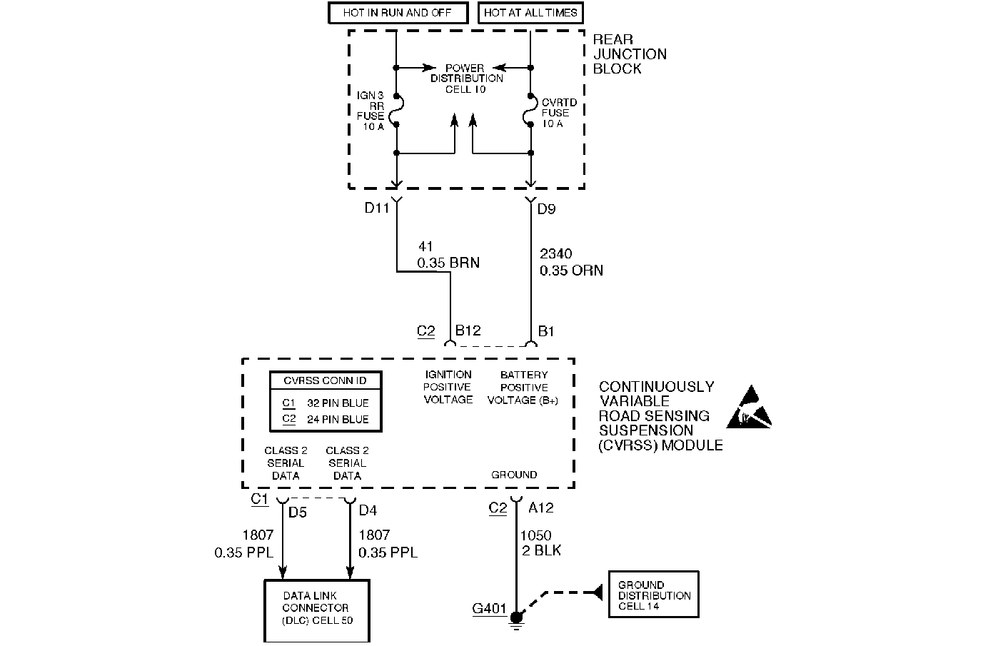
Circuit Description
The CVRSS module communicates to the other electronic control modules on the vehicle via the CLASS 2 serial bus.

Conditions for Setting the DTC
The DTC is also set when the power to the CVRSS module has been lost because of one or more of the following:
| • | loss of battery feed (loose terminals and/or fuses) |
| • | loss of ignition feed (loose terminals and/or fuses) |
| • | loss of a good CVRSS system ground |
| • | malfunction of the internal CVRSS module. |
The DTC is also set when the CVRSS module is powered and operational, but is unable to communicate with the IPC because of an open circuit condition, a short circuit condition to ground, or a short circuit condition to voltage on the CLASS 2 circuit.
The DTC turns HISTORY when the IPC can communicate with the CVRSS module.
Action Taken When the DTC Sets
| • | The SERVICE RIDE CONTROL message will be displayed. |
| • | The vehicle speed may be limited, or the STABILITY REDUCED message will be displayed. |
| • | DTC P1611, U1056 and/or U1255 can be stored. |
Conditions for Clearing the MIL/DTC
| • | Use the scan tool. |
| • | Use the On-Board diagnostic CLEAR RSS CODES feature. |
Test Description
Important: Do not backprobe the sensors, actuators, or any sealed connectors.
The number(s) below refer to the step number(s) on the diagnostic table.
Important: DTCs P1611, U1056, and U1255 can also be a result of:
• Electrical problems with the wiring harness. • Intermittent breaks in Class 2 communication caused by other controllers
and/or wiring harness issues.
-
This step checks for a blown ignition fuse.
-
This step checks for blown (open) battery fuse.
-
This step checks for an open circuit condition in the ground circuit.
-
This step checks for an open circuit condition in the battery circuit.
-
This step checks for an open circuit condition in the ignition circuit.
-
This step checks the CLASS 2 bus for a fault condition.
-
This step checks for a short circuit to ground condition in the ignition circuit.
-
This step checks for a short circuit to ground condition in the battery circuit.
Step | Action | Value(s) | Yes | No | ||||||
|---|---|---|---|---|---|---|---|---|---|---|
1 | Was the Road Sensing Suspension Diagnostic System Check performed? | -- | Go to Step 2 | |||||||
2 |
Is the fuse blown? | -- | Go to Step 13 | Go to Step 3 | ||||||
3 | Check the CVRTD (10 amp) fuse #32 (Rear Junction Block). Is the fuse blown? | -- | Go to Step 15 | Go to Step 4 | ||||||
4 |
Is the resistance the same or less than the specified value? | 5 ohms | Go to Step 6 | Go to Step 5 | ||||||
5 | Repair the open circuit condition in CKT 1050. Is the repair complete? | -- | -- | |||||||
6 |
Is the voltage above the specified value? | 10 V | Go to Step 8 | Go to Step 7 | ||||||
7 | Repair the open circuit condition in CKT 2340, or the Rear Junction Block. Is the repair complete? | -- | -- | |||||||
8 | Measure the voltage between the CVRSS module connector C2, terminal B12 (harness side), and ground with the DMM. Is the voltage above the specified value? | 10 V | Go to Step 10 | Go to Step 9 | ||||||
9 | Repair the open circuit condition in CKT 41, or the Rear Junction Block. Is the repair complete? | -- | -- | |||||||
10 |
Important: There are two class 2 serial data circuits. Check CKTs 1807 (at connector C1 terminals D4 and D5) for the following conditions:
Is a problem in CKT 1807 present? | -- | Go to Step 11 | Go to Step 12 | ||||||
11 | Repair the fault in CKT 1807. Is the repair complete? | -- | -- | |||||||
12 | Is DTC P1611 set? | -- | Go to Step 17 | |||||||
13 |
Is the resistance the same or less than the specified value? | 5 ohms | Go to Step 17 | Go to Step 19 | ||||||
14 | Repair the short circuit condition in CKT 141 and install a new fuse. Is the repair complete? | -- | -- | |||||||
15 |
Is the resistance the same or less than the specified value? | 5 ohms | Go to Step 17 | Go to Step 16 | ||||||
16 | Repair the short circuit condition in CKT 2340 and install a new fuse. Is the repair complete? | -- | -- | |||||||
17 | Measure the resistance from CVRSS control module connector C1, terminals D13, C12, C4 and C2, to ground with the DMM. Is the resistance the specified value for each circuit? | OL | Go to Step 19 | Go to Step 18 | ||||||
18 | Repair the short circuit condition in the affected circuit. Is the repair complete? | -- | -- | |||||||
19 |
Important: Check for intermittent connections on the fuses. Does the IPC display NO RSS DATA? | -- | Go to Step 20 | |||||||
20 |
Important: The CVRSS controller must be calibrated. Calibrate the CVRSS service controller using the scan tool. Refer to Electronic Suspension Control Module Calibration . Is the CVRSS control module calibrated? | -- | -- |
