For 1990-2009 cars only
Disassembly Procedure
- Remove the upper and lower shrouds from the steering column. Refer to Trim Covers, Shift Lever Seal Replacement - Off Vehicle
- The SIR coil assembly will become uncentered if:
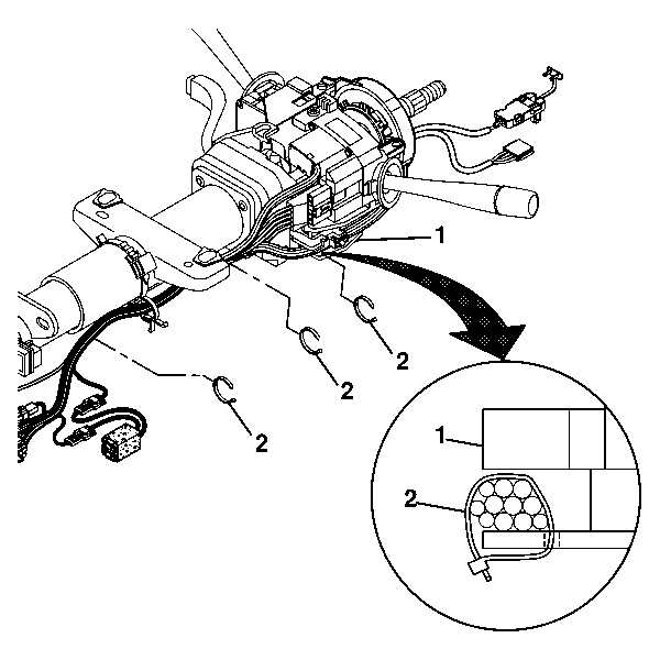
- Remove the three wire harness straps (2) from the steering column tilt head assembly (1).
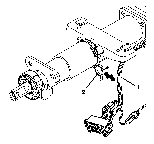
- Pop the wire harness assembly (1) from the wire harness strap (2).
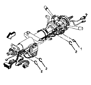
- When working on the power tilt and telescope column remove three wire harness straps (1). Remove one wire harness strap (1).
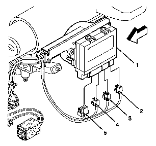
- When working on the power tilt and telescope column remove the green (5), brown (4), natural (3) and the black (2) connectors from the Steering Column interface module assembly (1).
- When working on the power tilt and telescope column remove the Steering Column interface module assembly (2) from the lower wire shield (1).
- When working on the power tilt and telescope column pop open the lower wire shield (1) to remove the wire harness assembly (2).
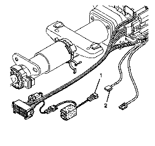
- Remove the black SIR connector (2) from the fused jumper assembly connector (1).
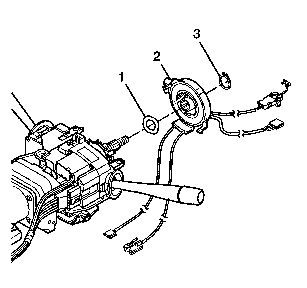
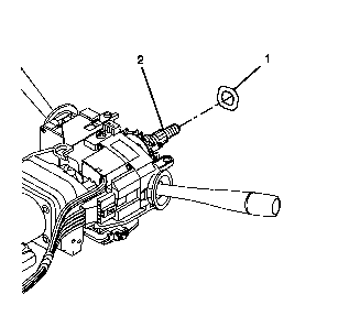
- Remove the retaining ring (3).
- Remove the SIR coil assembly (2).
- Remove the wave washer (1).
Important: If the SIR coil becomes uncentered, the ribbon may be damaged.
| • | The steering column is separated from the steering gear and allowed to rotate. |
| • | The centering spring is pushed down, letting the hub rotate while the coil is removed from the steering column. |
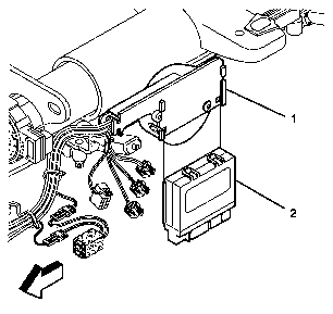
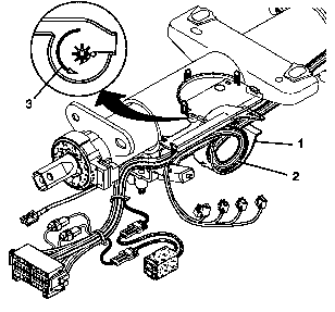
In the lower wire shield (1), notice which direction (3) and placement the wires are in.
Assembly Procedure
- Install the wave washer (1) to the race & upper shaft assembly (2).
- To install the SIR coil assembly:
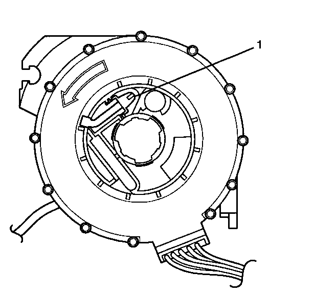
- Ensure the SIR coil assembly is centered. The new SIR coil assembly will be precentered. Pull the tab and remove. Do not depress the tab (1) on the back of the SIR coil assembly.
- Align the SIR coil assembly (1) with the horn tower on the turn signal cancel cam assembly (2).
- Install the retaining ring (1).
- Route the lower SIR coil assembly wires along the steering column jacket assembly.
- When working on the power tilt and telescope column install the wire harness assembly (2) into the lower wire shield (1).
- When working on the power tilt and telescope column slide the Steering Column interface module assembly (2) into the lower wire shield (1).
- When working on the power tilt and telescope column install the green (5), brown (4), natural (3) and the black (2) connectors into the Steering Column interface module assembly (1).
- Install the black SIR connector (2) to the fused jumper assembly connector (1).
- Pop the wire harness assembly (1) into the wire harness strap (2).
- Install the two wire harness straps (2). Install one wire harness strap (2) to the steering column tilt head assembly (1).
- When working on the power tilt and telescope column install the three wire harness straps (2) onto the wire harness assembly.
- Install the wire harness strap (1) into the steering column tilt head assembly.
- Install the upper and lower shrouds. Refer to Trim Covers, Shift Lever Seal Replacement - Off Vehicle
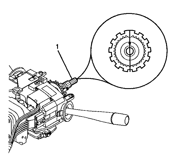
| • | Make sure the wheels are straight ahead. |
| • | Align the block tooth and the centering mark on the race & upper shaft assembly (1) at the 12 o' clock position. |
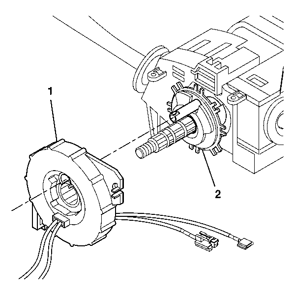
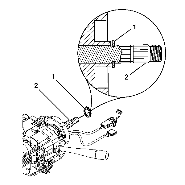
Important: The retaining ring (1) must seat securely on the groove of the race & upper shaft assembly (2).
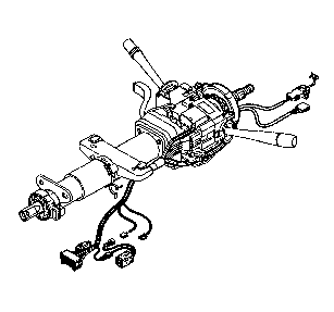

In the lower wire shield (1) notice the direction (3) and placement the wires go in.


