Removal Procedure
- Raise and support vehicle. Refer to Lifting and Jacking the Vehicle in General Information.
- Remove the tires and wheels. Refer to Tire and Wheel Removal and Installation in Tires and Wheels.
- Remove the exhaust system. Refer to Exhaust System Replacement in Engine Exhaust.
- Remove the rear coil springs. Refer to Coil Spring Replacement .
- Remove the rear disc brake rotors. Refer to Rear Brake Rotor Replacement in Disc Brakes.
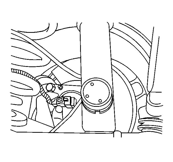
- Disconnect the wheel speed sensor electrical connector from each wheel.
- Remove the park brake cables. Refer to Parking Brake Rear Cable Replacement - Left Side and Parking Brake Rear Cable Replacement - Right Side in Park Brake.
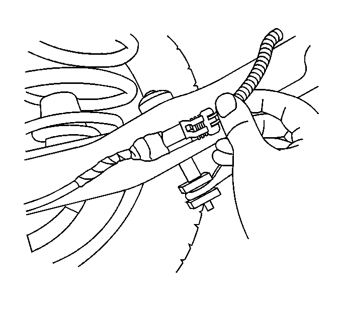
- Disconnect the electrical connectors from the support.
- Remove the road sensing suspension or automatic level control electrical connectors and vent hose.
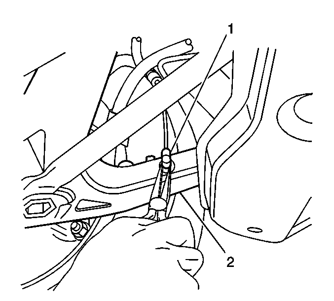
- Disconnect the road sensing suspension or automatic level control links (1) from the left and right control arms (2).
- Remove the automatic level control vent tube from the automatic level control compressor.
- Install a transmission jack to the support.
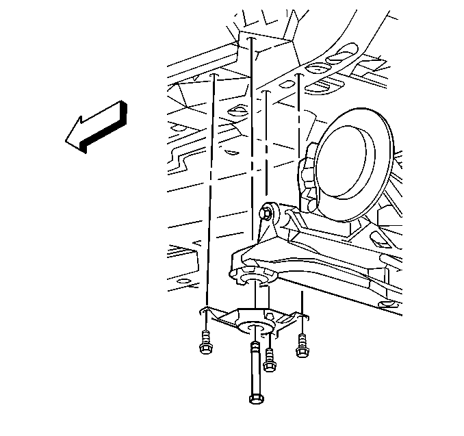
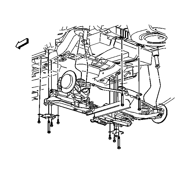
- Remove the support bracket retaining bolts from the body of the vehicle.
- Remove the front support mounting bolts and support brackets.
- Remove the rear support mounting bolts.
- With the aid of an assistant, lower the transmission jack in order to remove the support assembly from the vehicle.
- Transfer the necessary components.
Installation Procedure
- With the aid of an assistant, raise the transmission jack and install the support to the vehicle.
- Install the rear support mounting bolts to the body.
- Install the front support brackets and mounting bolts.
- Install the front bracket retaining bolts.
- Connect the automatic level control air tube to the automatic level control compressor.
- Connect the road sensing suspension or automatic level control electrical connectors and vent tube.
- Connect the electrical connectors to the support assembly.
- Connect the road sensing suspension or automatic level control link(s) (1) to both of the lower control arms (2).
- Install the park brake cables to the vehicle. Refer to Parking Brake Rear Cable Replacement - Left Side and Parking Brake Rear Cable Replacement - Right Side in Park Brake.
- Install the disc brake rotors to the vehicle. Refer to Rear Brake Rotor Replacement in Disc Brakes.
- Install the rear coil springs. Refer to Coil Spring Replacement .
- Install the exhaust system. Refer to Exhaust System Replacement in Engine Exhaust.
- Install the tires and wheels. Refer to Tire and Wheel Removal and Installation in Tires and Wheels.
- Lower the vehicle.
- Measure wheel alignment. Refer to Wheel Alignment Measurement in Wheel Alignment.

Notice: Use the correct fastener in the correct location. Replacement fasteners must be the correct part number for that application. Fasteners requiring replacement or fasteners requiring the use of thread locking compound or sealant are identified in the service procedure. Do not use paints, lubricants, or corrosion inhibitors on fasteners or fastener joint surfaces unless specified. These coatings affect fastener torque and joint clamping force and may damage the fastener. Use the correct tightening sequence and specifications when installing fasteners in order to avoid damage to parts and systems.
Tighten
Tighten the support mounting bolts to 191 N·m (141 lb ft).

Tighten
Tighten the front bracket retaining bolts to 86 N·m (63 lb ft).


