Tools Required
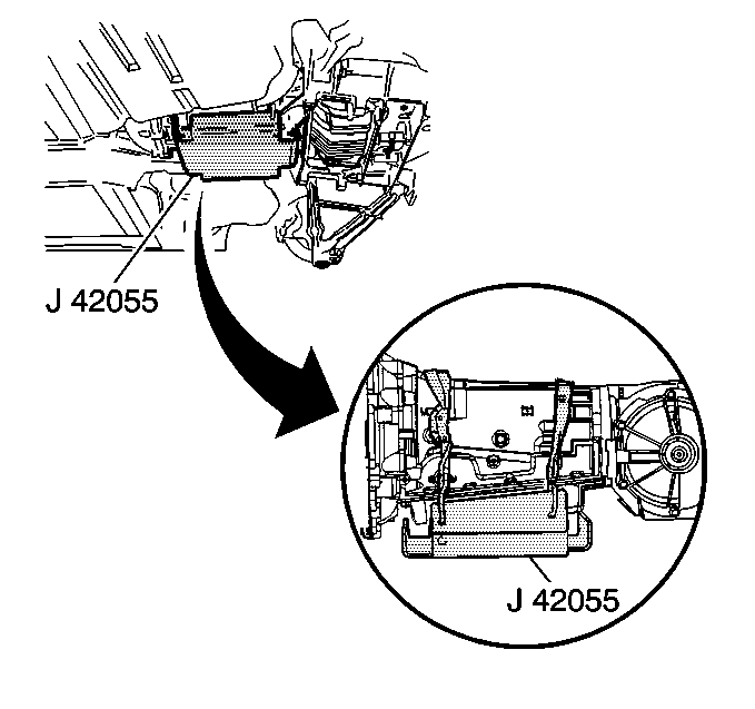
J 42055 Transmission Support Fixture
Removal Procedure
Notice: Failure to follow the proper removal and installation procedures may result in damage to the engine crankshaft thrust bearing.
Notice: When lowering and removing the rear of the driveline, observe the clearance between the rear of the transaxle assembly and the underbody to prevent damage.
- Disconnect the negative battery cable.
- Raise and suitably support the vehicle. Refer to Lifting and Jacking the Vehicle in General Information.
- Remove the rear tire and wheel assemblies. Refer to Tire and Wheel Removal and Installation in Tires and Wheels.
- Remove the intermediate pipe. Refer to Intermediate Pipe Replacement in Engine Exhaust.
- Remove the LH muffler assembly. Refer to Exhaust Muffler Replacement - Left Side in Engine Exhaust.
- Remove the RH muffler assembly. Refer to Exhaust Muffler Replacement - Right Side in Engine Exhaust.
- Disconnect the rear park brake cables from the actuator levers. Refer to Parking Brake Rear Cable Replacement in Park Brake.
- Disconnect the rear wheel speed sensor electrical connectors to the wheel speed sensors.
- Disconnect the electrical connectors from the suspension rear position sensors.
- Disconnect the suspension rear position sensor servo arms from the lower control arms. Refer to Electronic Suspension Rear Position Sensor Replacement in Electronic Suspension Control (ESC).
- Remove the rear brake calipers from the caliper brackets. Support the RH rear caliper to the lower control arm and the LH rear caliper to the body with heavy mechanic's wire or equivalent; ensure that there is no tension on the hydraulic brake flexible hose. Do NOT disconnect the hydraulic brake flexible hose from the caliper. Refer to Rear Brake Caliper Replacement in Disc Brake.
- Disconnect the RH rear brake pipe at the union on the LH side of the transmission.
- Plug the openings in the brake pipe to prevent fluid loss and contamination.
- Remove the drive axle spindle nuts.
- Support the lower control arm with a straight jack.
- Disconnect the outer tie rod end from the suspension knuckle. Refer to Tie Rod Replacement in Rear Suspension.
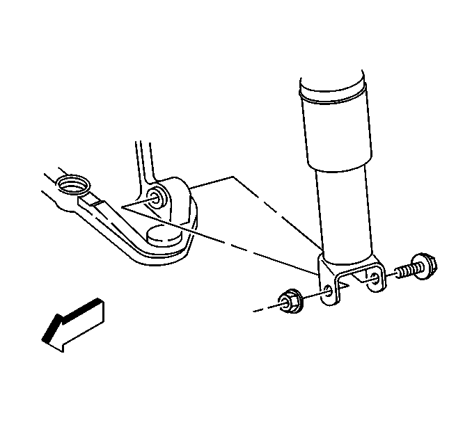
- Remove the shock absorber lower mounting bolt.
- Disconnect the upper ball joint from the suspension knuckle. Refer to Knuckle Replacement in Rear Suspension.
- Remove the straight jack from the control arm.
- Repeat steps 13 through 17 for the other side of the vehicle.
- Remove the vibration damper. Refer to Drive Line Vibration Dampener Replacement in Propeller Shaft.
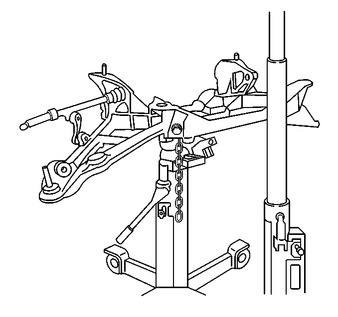
- Assemble the J 42055 .
- Install the J 42055 to a transmission jack.
- Position and firmly secure the J 42055 with the transmission jack to the transmission.
- Disconnect the wiring harness, wiring ground, and brake pipe clip retainers from the rear suspension crossmember.
- Position the RH side wiring harness through the cradle and position aside.
- Remove the transaxle mount to side crossmember nuts.
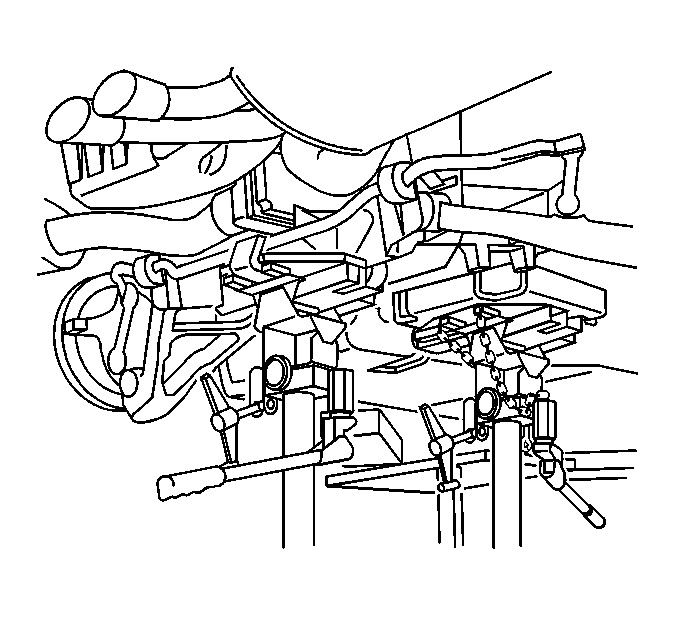
- Position a transmission jack under the rear suspension crossmember and firmly secure the crossmember to the jack.
- Using ONLY HAND TOOLS, remove the rear suspension crossmember retaining nuts.
- With the aid of an assistant, slowly lower the rear suspension crossmember away from the vehicle frame rails and remove the crossmember.
- Remove the rear wheel drive shafts from the rear transaxle. Refer to Wheel Drive Shaft Replacement in Wheel Drive Shafts.
- Remove the differential to transmission bolts and nuts.
- Place a suitable jack under the rear differential.
- SLOWLY slide the differential from the transmission.
- SLOWLY lower the rear differential completely out of the vehicle.
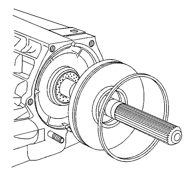
- Remove the O-ring from the differential.
Caution: Refer to Battery Disconnect Caution in the Preface section.
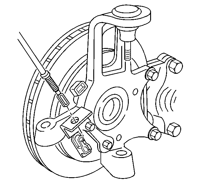
Notice: Support the brake caliper with heavy mechanic wire, or equivalent, whenever it is separated from its mount and the hydraulic flexible brake hose is still connected. Failure to support the caliper in this manner will cause the flexible brake hose to bear the weight of the caliper, which may cause damage to the brake hose and in turn may cause a brake fluid leak.
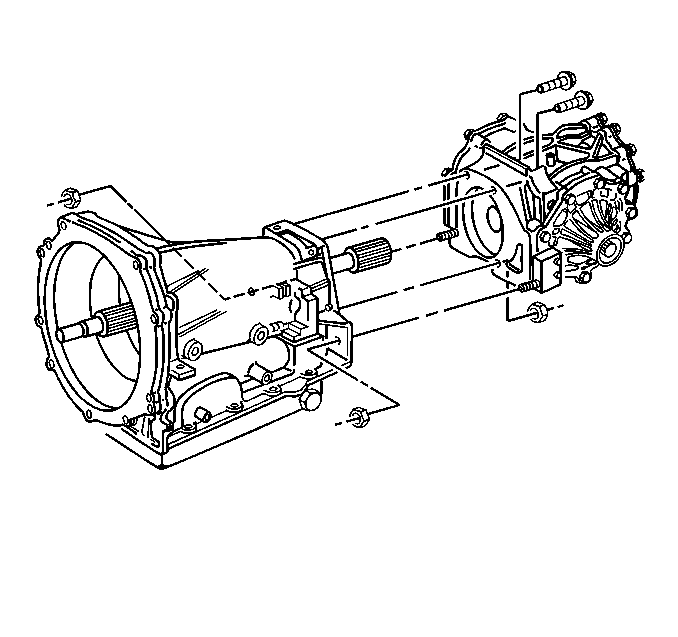
Important: Use care when separating the differential from the transmission to not damage the transmission output shaft seal in the differential plate.
Installation Procedure
- Install the O-ring to the differential.
- Raise the rear differential into the vehicle.
- SLOWLY slide the differential to the transmission.
- Install the differential to transmission bolts and nuts.
- Remove the jack from under the rear differential.
- Install the rear wheel drive shafts. Refer to Wheel Drive Shaft Replacement in Wheel Drive Shafts.
- With the aid of an assistant, begin to raise the rear suspension crossmember (still firmly attached to a transmission jack), to the vehicle frame rails.
- Guide the rear suspension crossmember alignment pins into the alignment holes in the vehicle frame rails, and guide the transaxle mount studs into the mounting holes in the crossmember, then raise the crossmember to seat to the frame rails.
- Using ONLY HAND TOOLS, install NEW rear suspension crossmember mounting nuts.
- Remove the transmission jack from the rear suspension crossmember.
- Release the J 42055 from the transmission, then remove the J 42055 and transmission jack.
- Install the transaxle mount to rear suspension crossmember nuts.
- Install the vibration damper. Refer to Drive Line Vibration Dampener Replacement in Propeller Shaft.
- Reposition the RH side wiring harness through the cradle and position back.
- Connect the wiring harness, wiring ground, and brake pipe clip retainers to the rear suspension crossmember.
- Support the lower control arm with a jack.
- Connect the upper ball joint to the suspension knuckle. Refer to Knuckle Replacement in Rear Suspension.
- Install the shock absorber lower mounting bolt.
- Connect the outer tie rod end to the suspension knuckle. Refer to Tie Rod Replacement in Rear Suspension.
- Remove the jack from the suspension control arm.
- Repeat steps 19 through 23 for the other side of the vehicle.
- Install the drive axle spindle nuts.
- Remove the plugs from the brake pipe openings.
- Connect the RH rear brake pipe at the union.
- Remove the mechanics wire supporting the rear calipers and install calipers to the caliper brackets. Refer to Rear Brake Caliper Replacement in Disc Brake.
- Connect the suspension rear position sensor servo arms to the lower control arms. Refer to Electronic Suspension Rear Position Sensor Replacement in Electronic Suspension Control (ESC).
- Connect the electrical connectors to the suspension rear position sensors.
- Connect the rear wheel speed sensor electrical connectors to the wheel speed sensors.
- Connect the rear park brake cables to the actuator levers. Refer to Parking Brake Rear Cable Replacement in Park Brake.
- Install the RH muffler assembly. Refer to Exhaust Muffler Replacement - Right Side in Engine Exhaust.
- Install the LH muffler assembly. Refer to Exhaust Muffler Replacement - Left Side in Engine Exhaust.
- Install the intermediate pipe. Refer to Intermediate Pipe Replacement in Engine Exhaust.
- Install the rear tire and wheel assemblies. Refer to Tire and Wheel Removal and Installation in Tires and Wheels.
- Lower the vehicle.
- Connect the negative battery cable.
- Program the transmitters. Refer to Transmitter Programming in Keyless Entry.
- Bleed the brake system. Refer to Hydraulic Brake System Bleeding in Hydraulic Brakes.

Notice: Refer to Fastener Notice in the Preface section.
Tighten
Tighten the differential to transmission bolts and nuts to 50 N·m
(37 lb ft).


Tighten
Tighten the side suspension crossmember mounting nuts to 110 N·m
(81 lb ft).

Tighten
Tighten the transaxle mount to side suspension crossmember nuts to 50 N·m
(37 lb ft).

Tighten
Tighten the rear shock absorber lower mounting bolt to 220 N·m
(162 lb ft).
Tighten
Tighten the driveline support assembly front plug bolts to 160 N·m
(118 lb ft).
Tighten
Tighten the brake pipe to 18 N·m (13 lb ft).

Tighten
Tighten the negative battery cable bolt to 15 N·m (11 lb ft).
