Removal Procedure
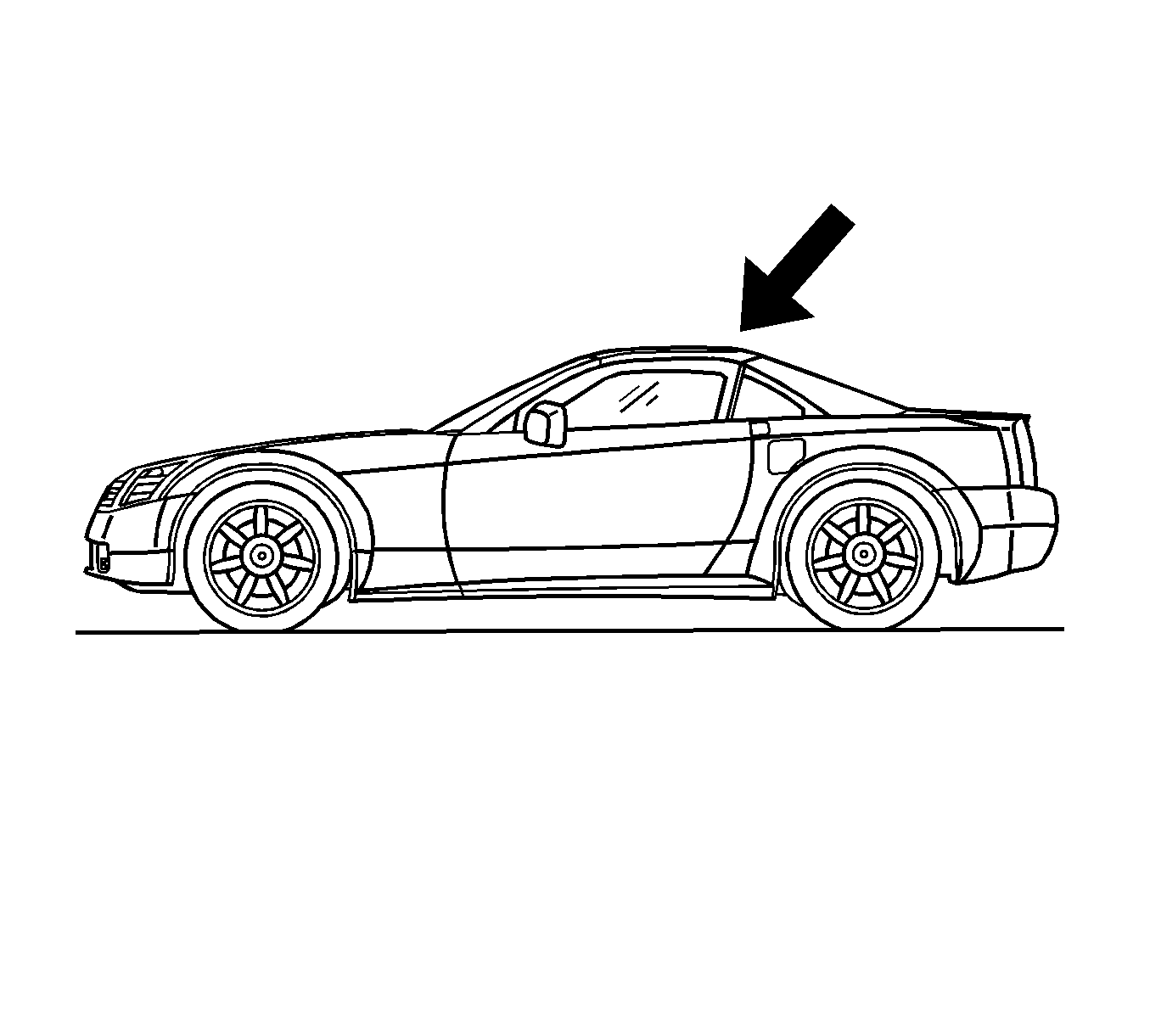
- Place the folding top in the up position.
- Disconnect the battery. Refer to Battery Negative Cable Disconnection and Connection in Engine Electrical.
- Remove the left side compartment side trim. Refer to Rear Compartment Side Trim Replacement - Left Side in Body Rear End.
- Remove the right side compartment side trim. Refer to Rear Compartment Side Trim Replacement - Right Side in Body Rear End.
- Remove the release actuator from the fuel filler door. Refer to Fuel Tank Filler Door Lock Actuator Replacement in Body Rear End.
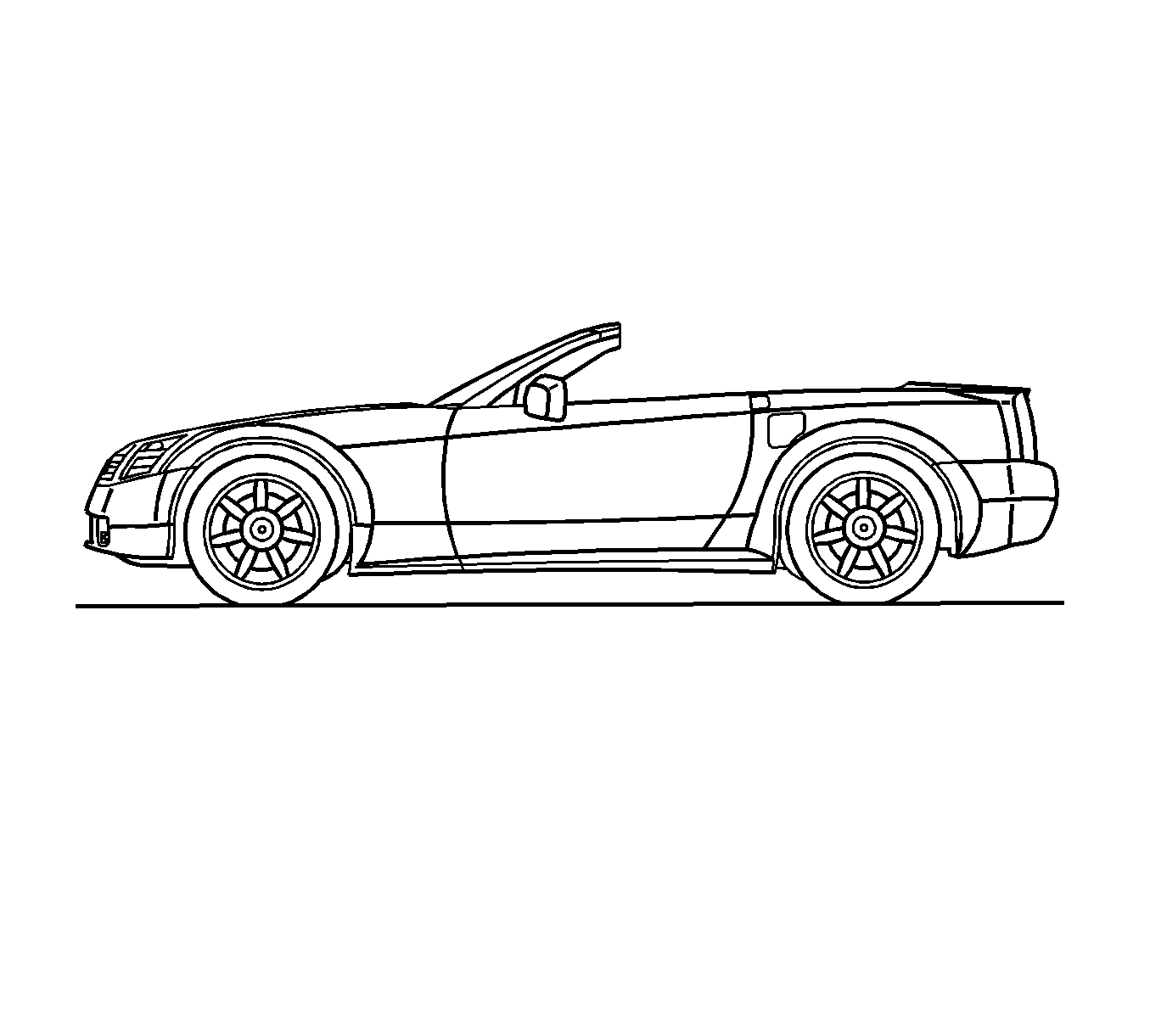
- Manually place the folding top in the down position. Refer to Folding Top Manual Operation .
- Remove the left side seat belt retractor. Refer to Seat Belt Retractor Replacement - Left Front in Seat Belts.
- Remove the right side seat belt retractor. Refer to Seat Belt Retractor Replacement - Right Front in Seat Belts.
- Remove the ignition lock key transmitter antennas. Refer to Ignition Lock Key Transmitter Antenna Replacement - Left Side and to Ignition Lock Key Transmitter Antenna Replacement - Right Side in Entertainment.
- If the vehicle is equipped with a digital radio remove the digital radio receiver. Refer to Digital Radio Receiver Replacement in Entertainment.
- Open the rear compartment.
- Remove both of the quarter panels. Refer to Rear Quarter Panel Replacement in Body Rear End.
- Remove both of the rear compartment frames. Refer to Rear Compartment Panel Frame Replacement in Collision Repair.
- Measure 5 mm (3/16 in) down from the weatherstrip pushpin holes (3).
- Scribe a section line (4) across the panels as shown.
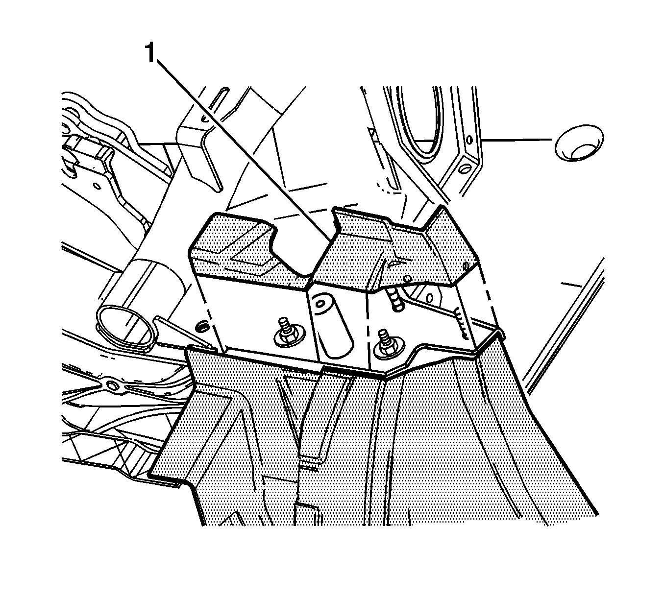
- Using a reciprocating saw or equivalent tool, cut through both panels following the section line (4).
- Remove and save the sectioned part (1) for the installation procedure.
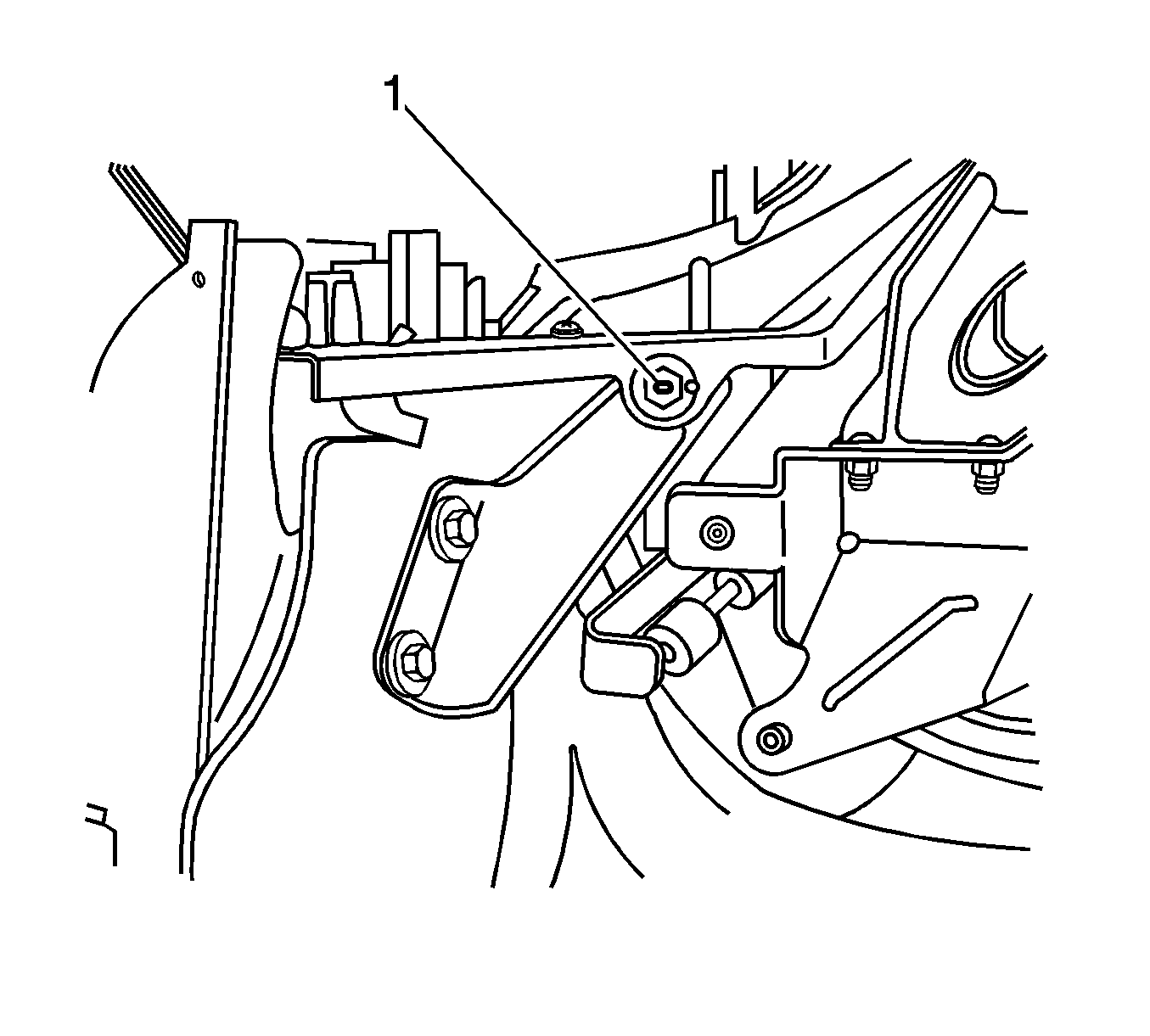
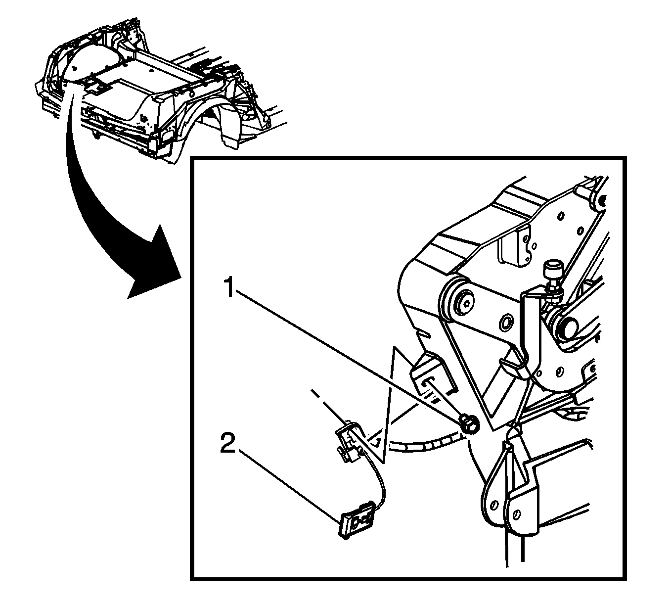
- Remove the roof support bracket bolt (1).
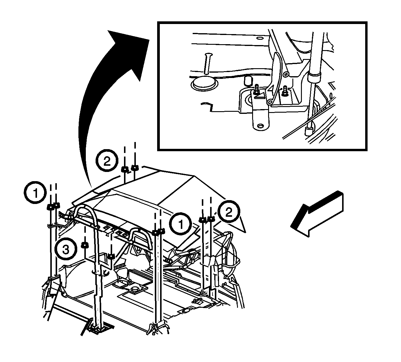
- Remove the nuts (1) from the outer roof support bracket.
- Remove the nuts (3) from the center roof support bracket.
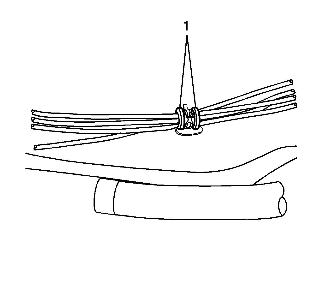
- Open the fold-over clips (1) on the rear end panel that retain the hydraulic hoses and remove the hoses.
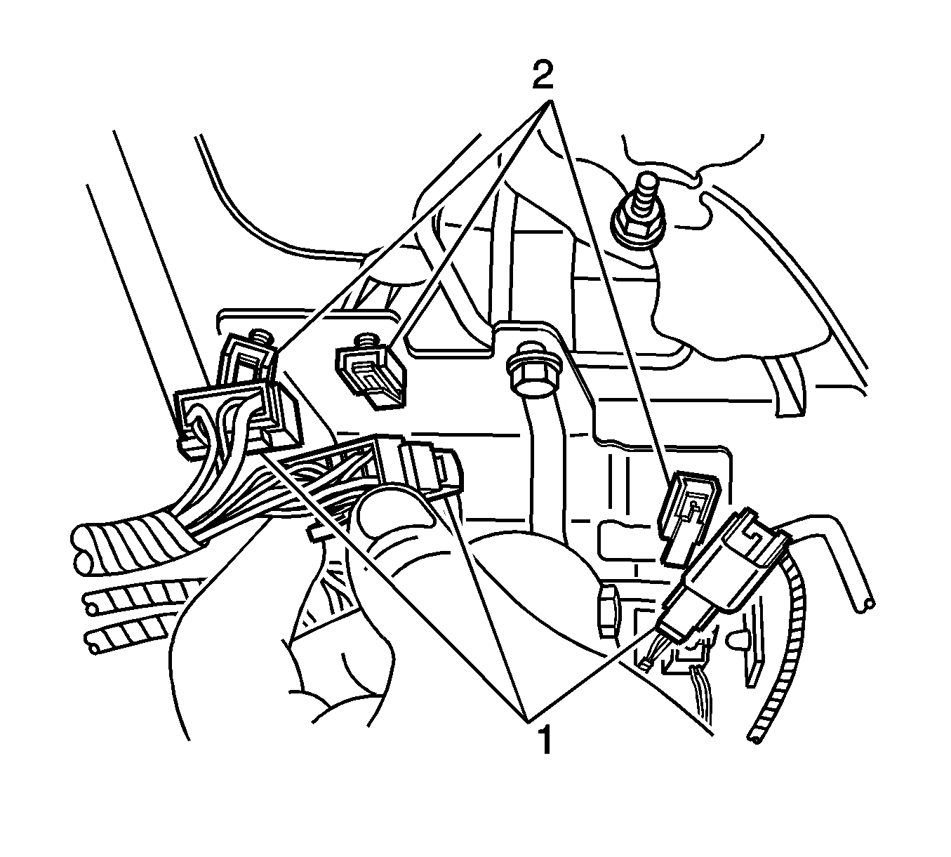
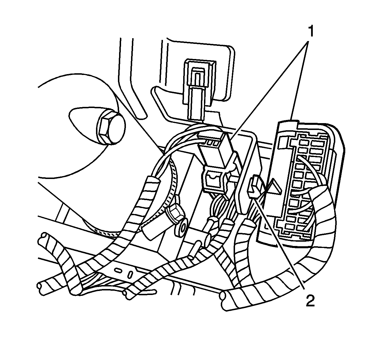
- Remove the 3 electrical connectors (1) from the hydraulic pump bracket (2).
- Remove the 2 electrical connectors from the hydraulic pump bracket.
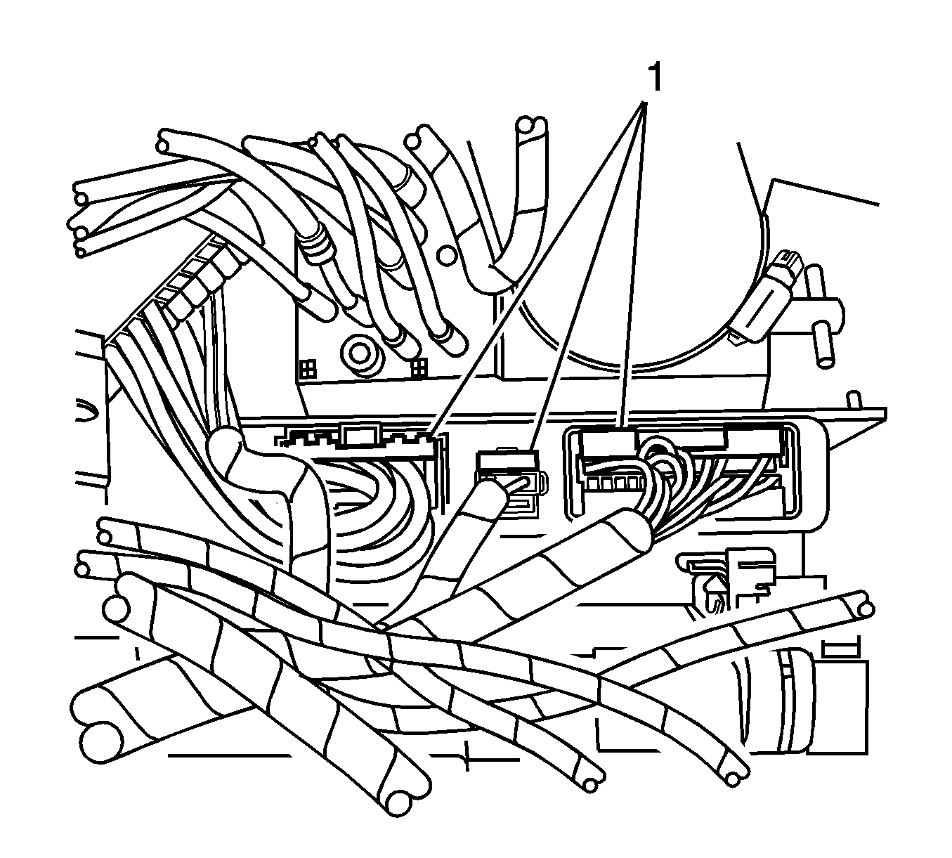
- Disconnect the 3 electrical connectors (1) from the folding top control module.
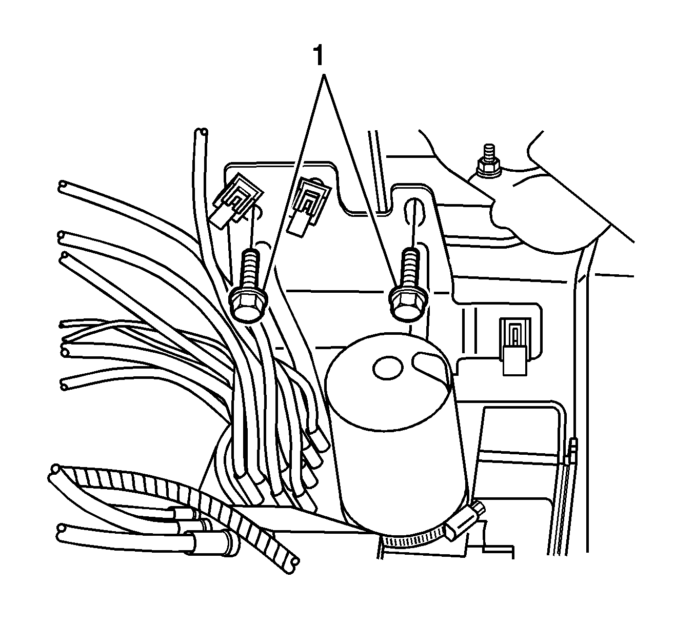
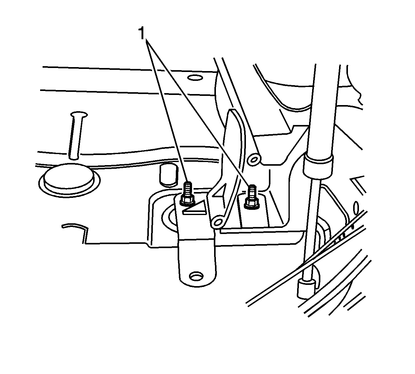
- Remove the hydraulic pump bracket bolts (1).
- Lift the hydraulic pump up and out of the storage compartment and set the pump in the rear compartment.
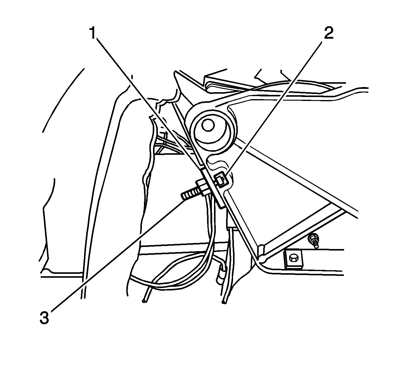
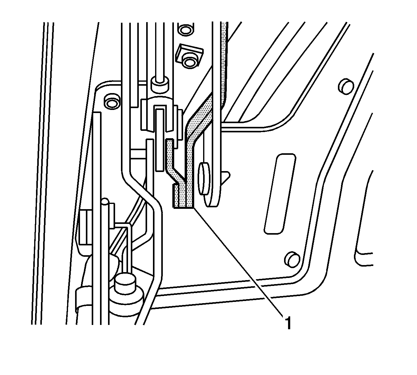
- Remove the fastener (1) from the retaining bracket that holds the rear mounted door release cable (2).
- If you will install a new folding top module, proceed to step 35.
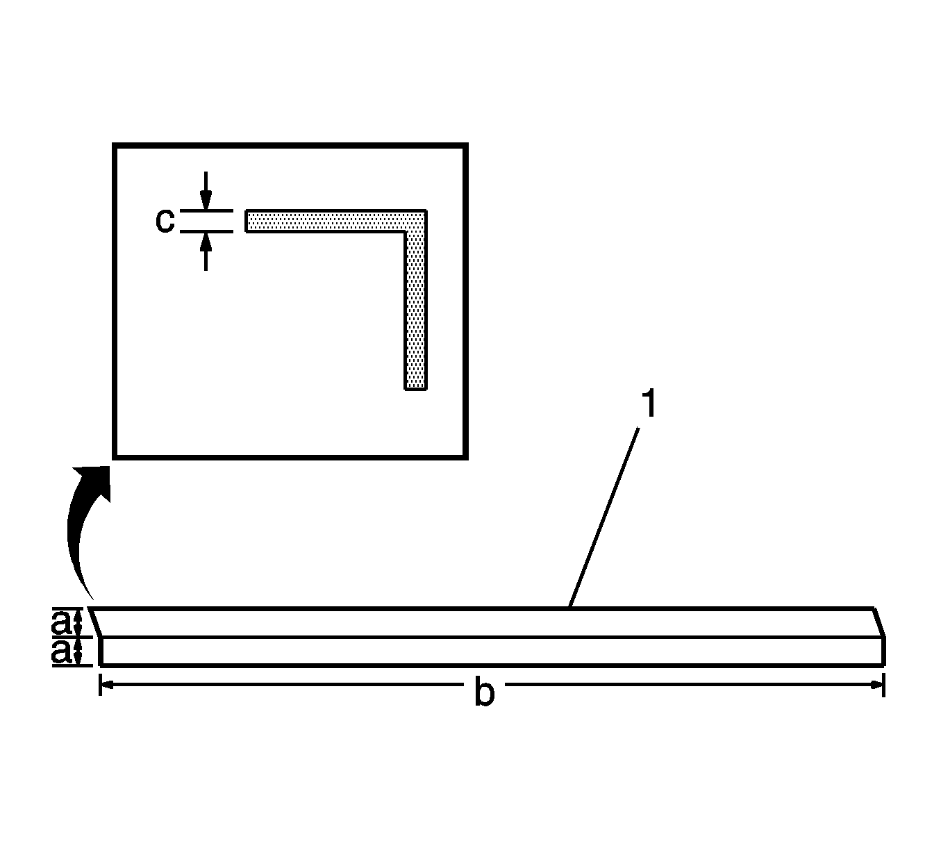
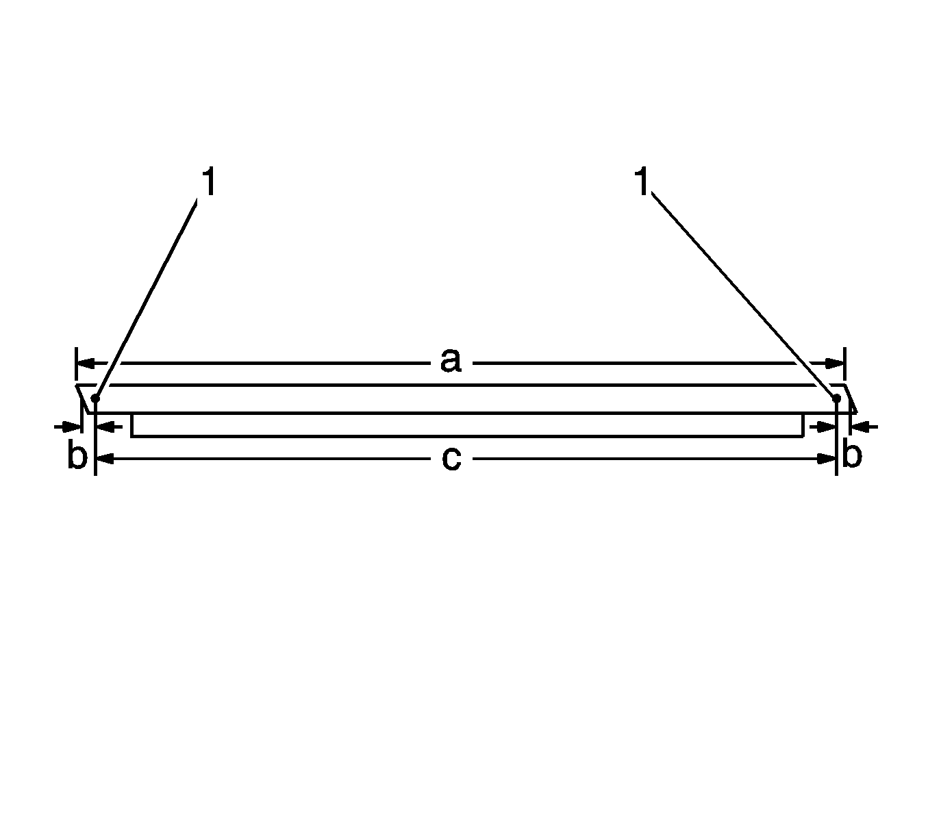
- Begin with a piece of angle iron (1) of length (b) 1448 mm (57 in), of width (a) 50x50 mm (2x2 in) with a minimum wall stock (c) of 3 mm (1/8 in).
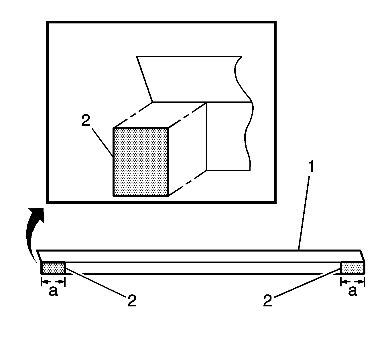
- Cut off a section (2) of 80 mm (3 1/8 in) from one flange on both sides of the angle iron (1).
- Drill 2 holes (1) 10 mm (3/8 in) in the center of the flange that was left full length. Place each hole 12.7 mm (½ in) from the outside edge of the flange. The centers of the 2 holes should be 1422 mm (56 in) apart.
- Place a 6x25 mm bolt (1) in the slots (2) in the rear face of the 2 frame supports.
- Install the support bar on the bolts in the frame supports.
- Install a washer and nut on the 2 bolts and tighten.
- Remove the nuts (1) from the rear roof support bracket.
- Attach the hydraulic pump to the support bracket with wire ties.
- Attach any excess slack in the wiring or the hydraulic hoses to the support bracket with wire ties.
- Select a location to place the folding top module after you have lifted the module from the vehicle.
- Remove the folding top module from the vehicle. If a hoist is not used, you will require the aid of 6 assistants. Lift the module at each corner.
- Note the quantity and the location of any shims that my be present at any of the mounting locations.
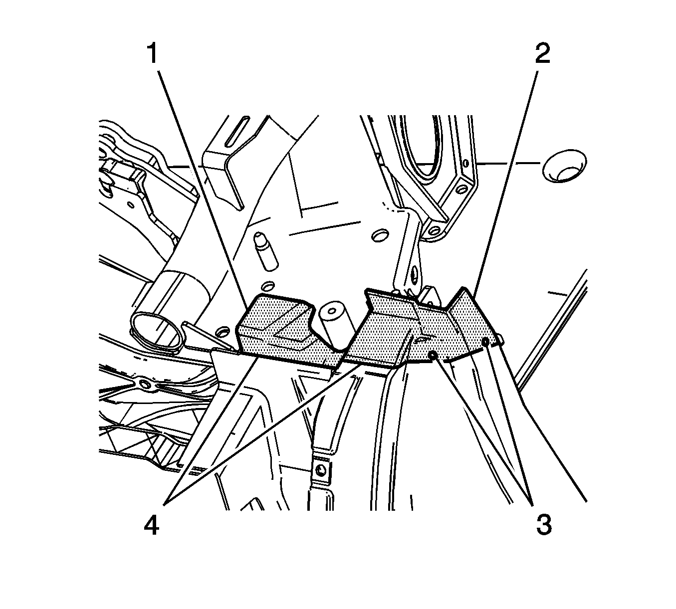
Important: In order to remove the folding top module, first remove a section of the bodyside reinforcement (1) and the bodyside (2). The bodyside and the reinforcement are bonded together, so you will remove the components as a single unit.
Important: Save the section part for the installation procedure.
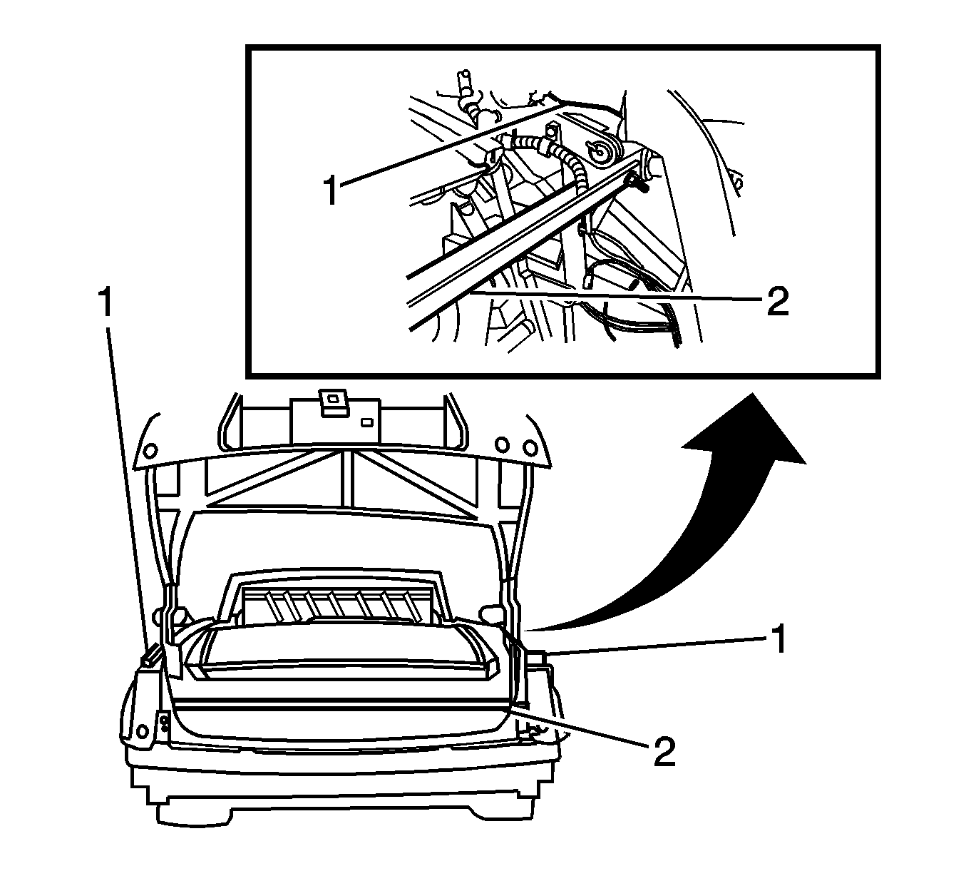
If you will reinstall the same folding top module, you must first make an angle iron support bar (2) in order to secure the distance between the 2 quarter longitudinal frame supports (1) at the top rear of the roof assembly. The following steps show how to make the support bar.
Installation Procedure
- Install the same shims in the original locations.
- Open the rear compartment.
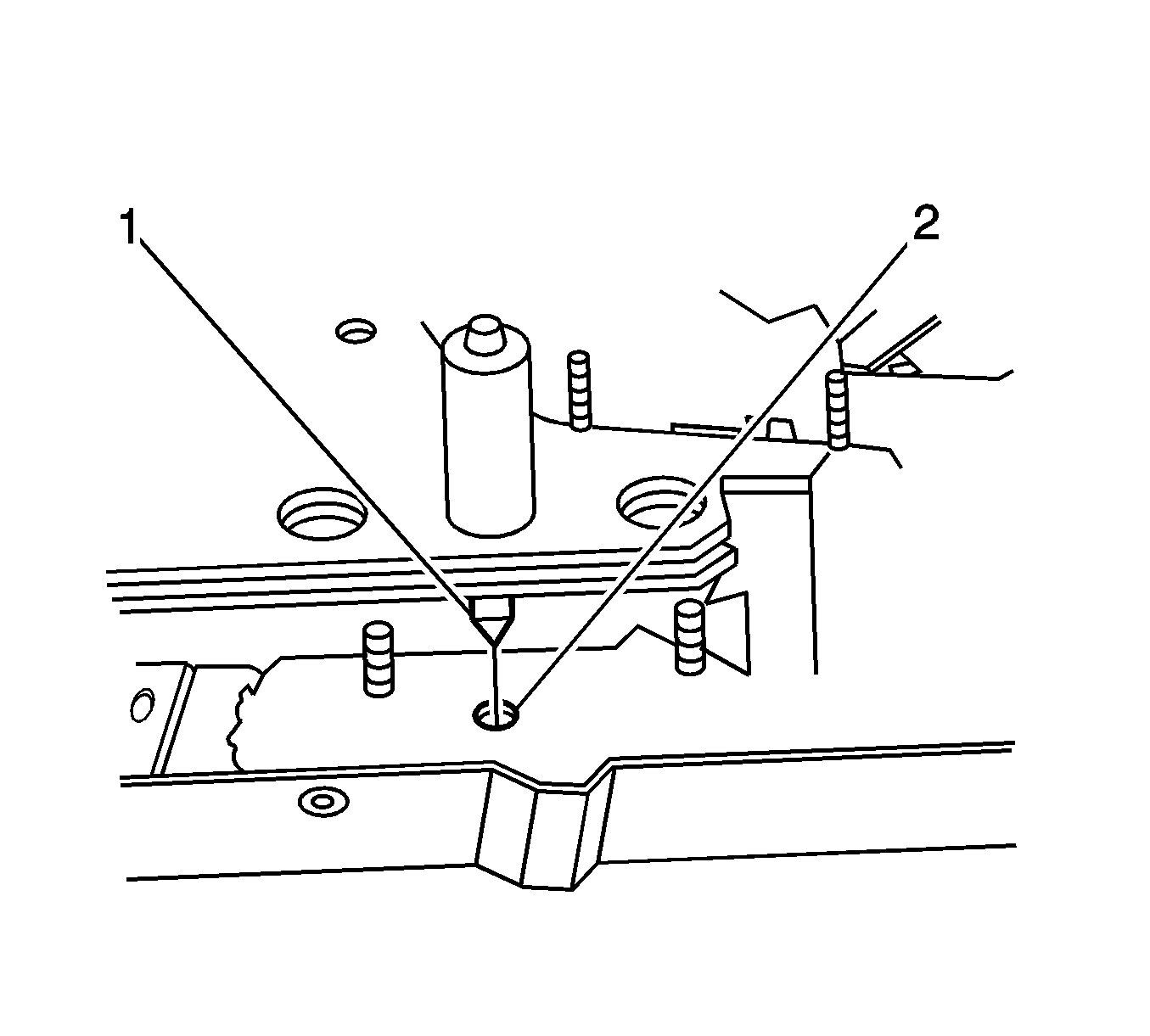
- Position the folding top module to the vehicle and align the front locating pins (1) to the holes (2) in the B-pillars while lowering the module into place.
- Install the nuts on the folding top module and hand tighten the nuts in the designated sequence.
- Install the roof support bracket bolt (1).
- Cut the tie wraps holding the hydraulic hoses and the electrical wires to the shipping bar.
- Remove the hydraulic pump from the shipping bar.
- Remove the shipping bar from the roof module.
- Position the hydraulic pump to the mounting location.
- Apply LOCTITE™ Blue, GM P/N 12345382 (Canadian P/N 10953489) or equivalent to the bolts.
- Install the bolts (1) to the hydraulic pump bracket.
- Connect the 3 electrical connectors (1) to the folding top control module.
- Install the 2 electrical connectors (1) to the hydraulic pump bracket (2).
- Install the 3 electrical connectors (1) to the hydraulic pump bracket (2).
- Install the hydraulic hoses in the fold-over clips (1) on the rear end panel. Fold the clips over to retain the hydraulic hoses.
- Install the fastener (1) to the bracket retaining the rear door release cable (2).
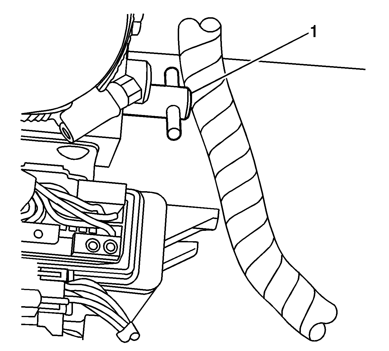
- Turn the hydraulic pump bypass valve (1) counterclockwise until the valve stops.
- Pull the over-center links (1) down to unlock the storage compartment panel.
- Move the storage compartment panel rearward and up to the stored position. Pull on the center of the panel to maintain even pressure. The rubber bumpers on each corner of the panel will fit against the underside on the rear compartment lid.
- Push both sides of the over-center links up to lock the storage compartment panel.
- Push up on the over-center link (1) until the closeout panels start to move.
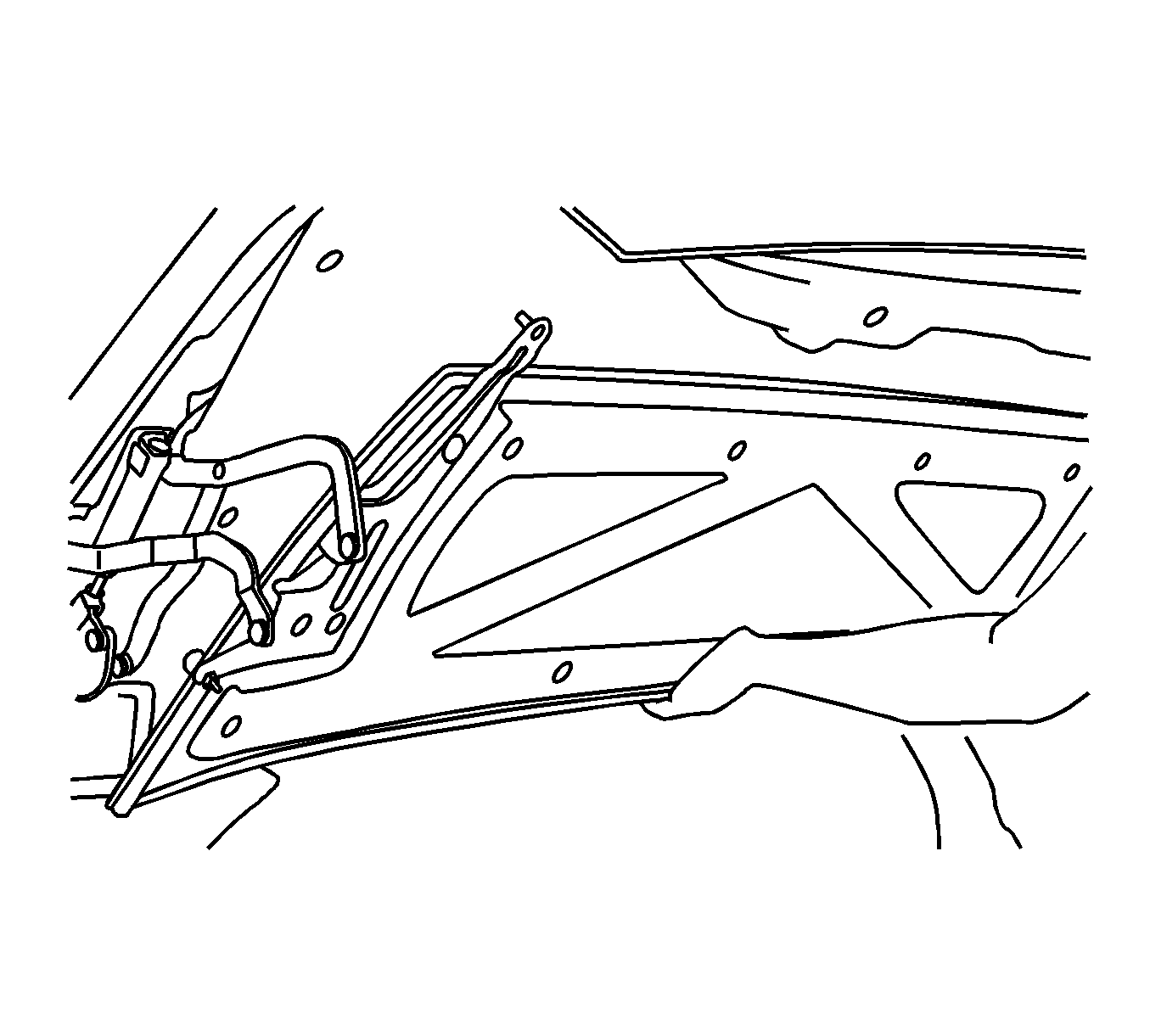
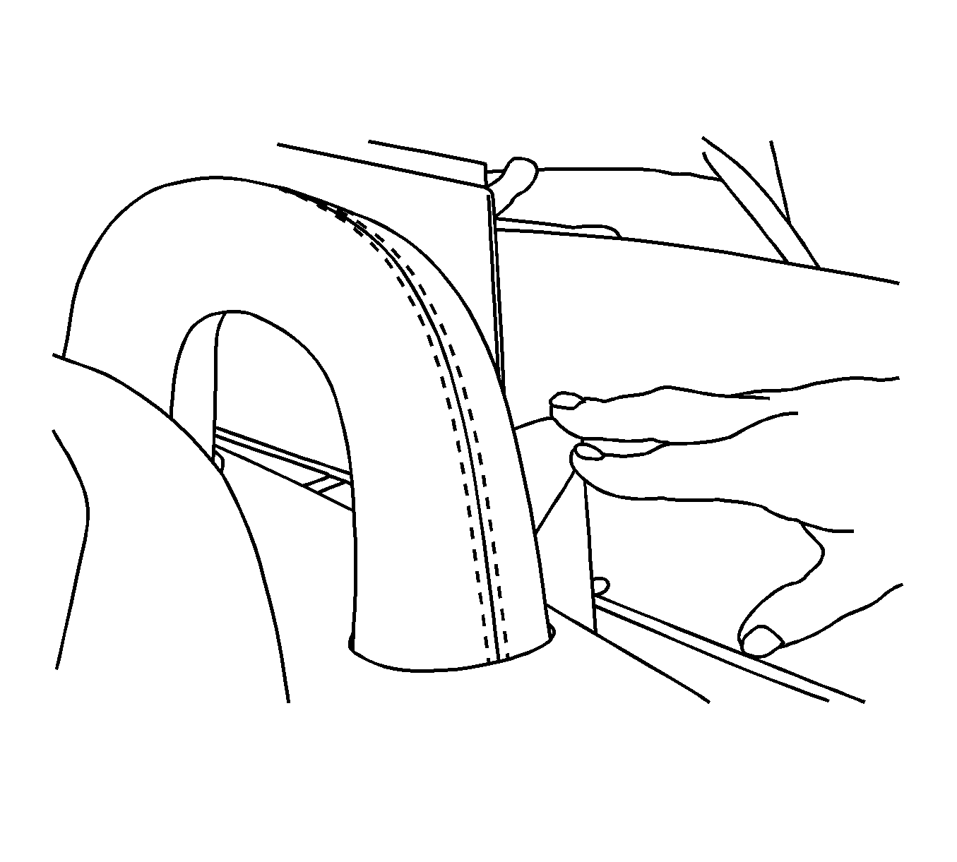
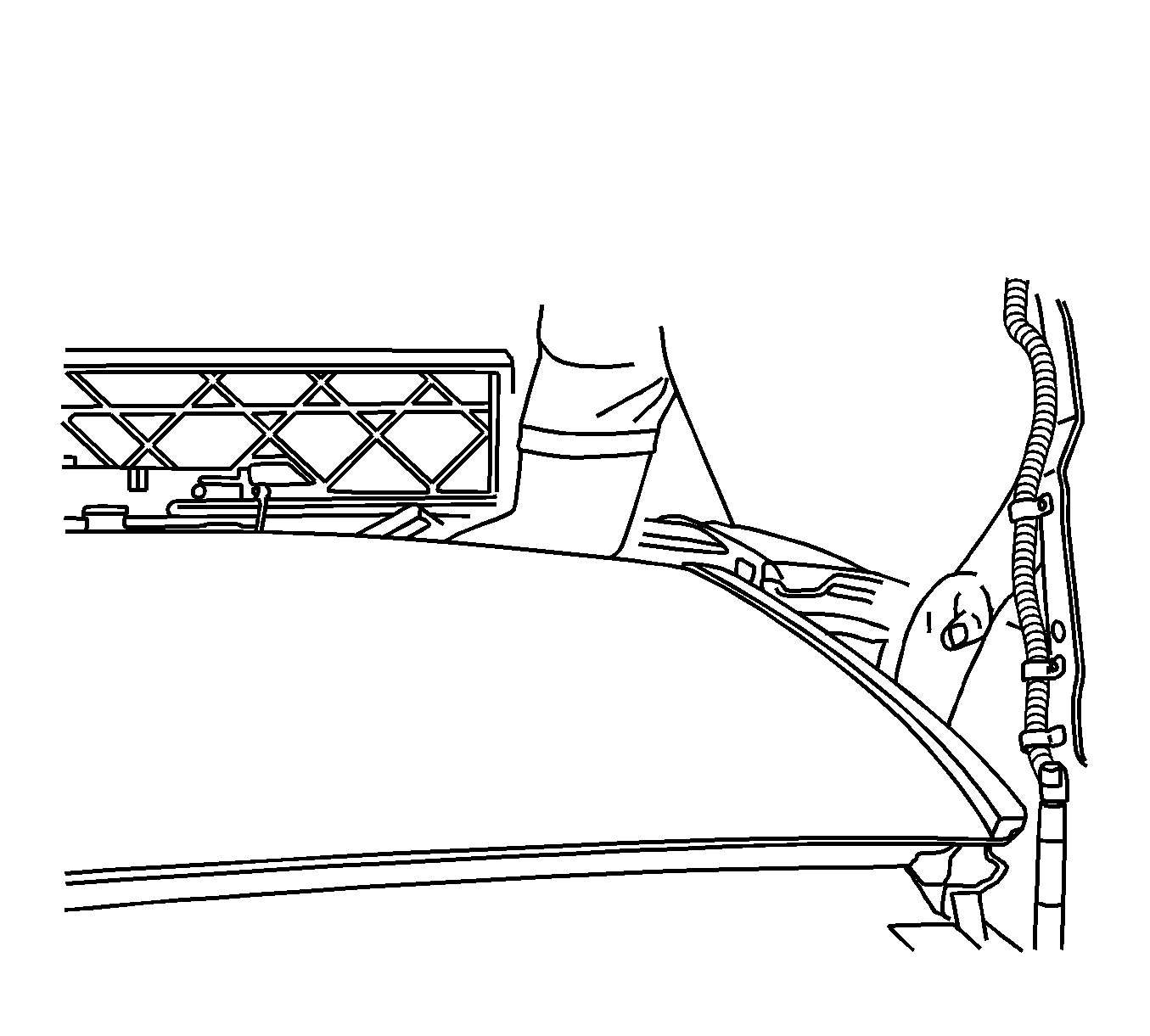
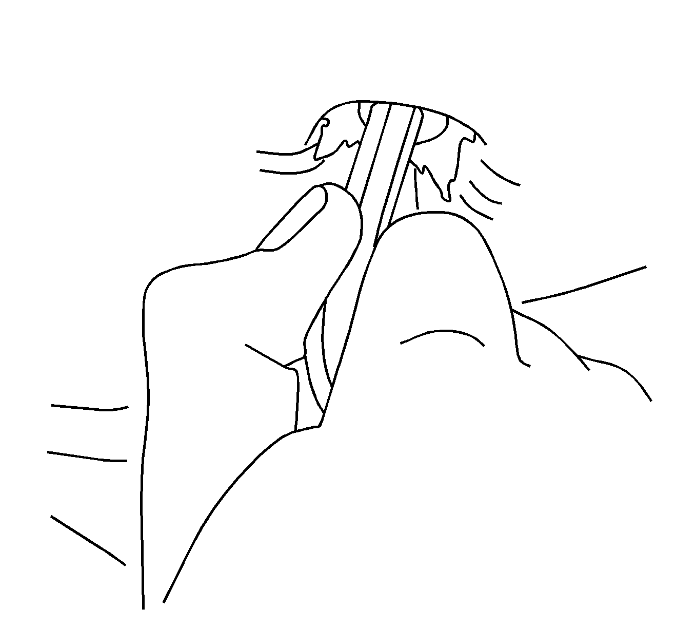
- Grasp the compartment closeout panel and pull open with one hand. Use your other hand to assist one of the closeout outer panels to an open position.
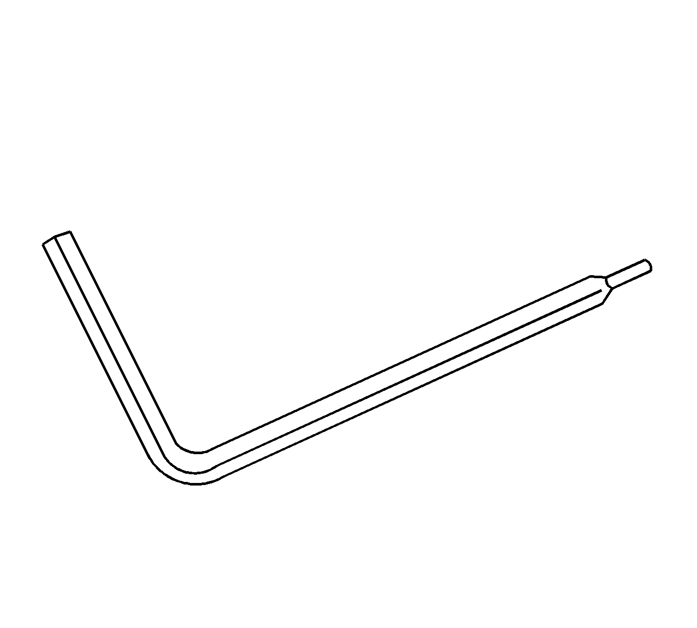
- Remove the wrench located inside the passenger side storage compartment.
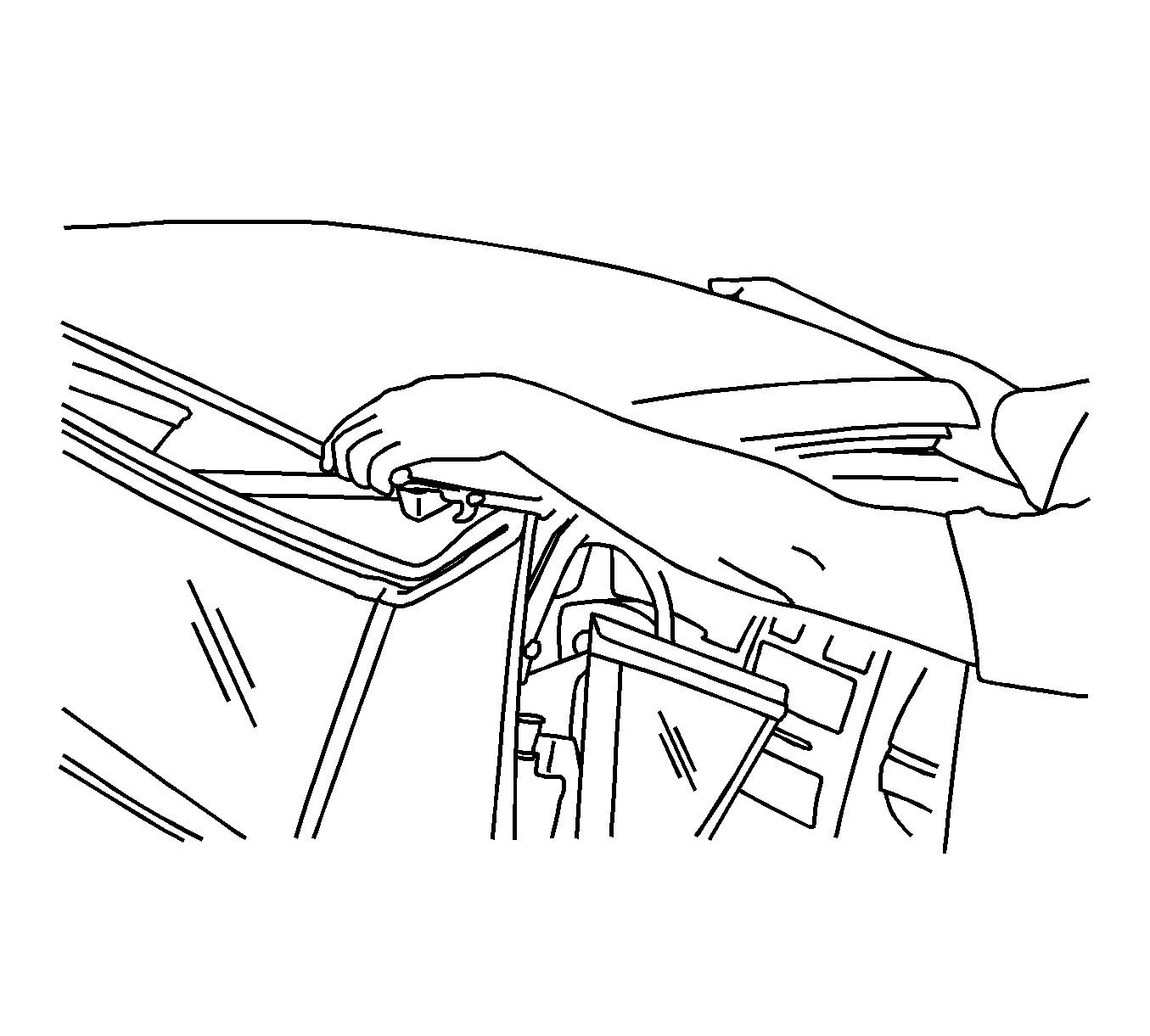
- Reach in from the side of the vehicle and under the top to remove the headliner plug. The plug is located in the center of the top near the front.
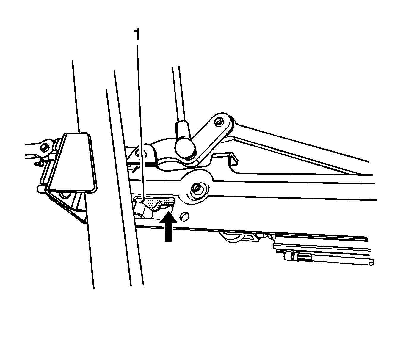
- Insert the wrench into the latch actuator bolt beneath the plug location. Turn the wrench counterclockwise until movement stops, while gently pulling up on the center of the folding top to release the top.
- Grasp the folding top at the front and at the side. Lift the folding top out of the stored position.
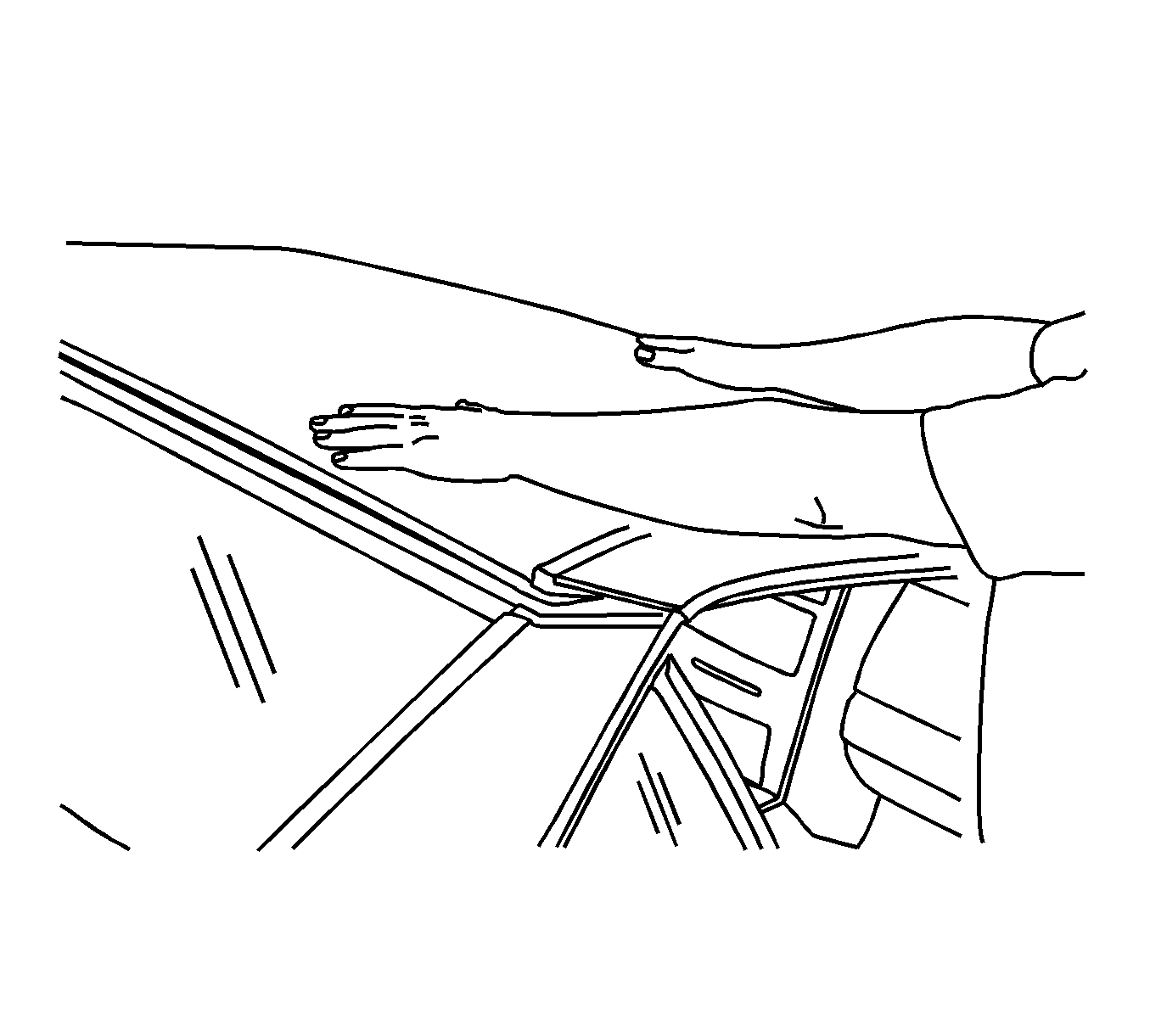
- Move the folding top towards the windshield header. Be careful not to pinch your fingers between the panels.
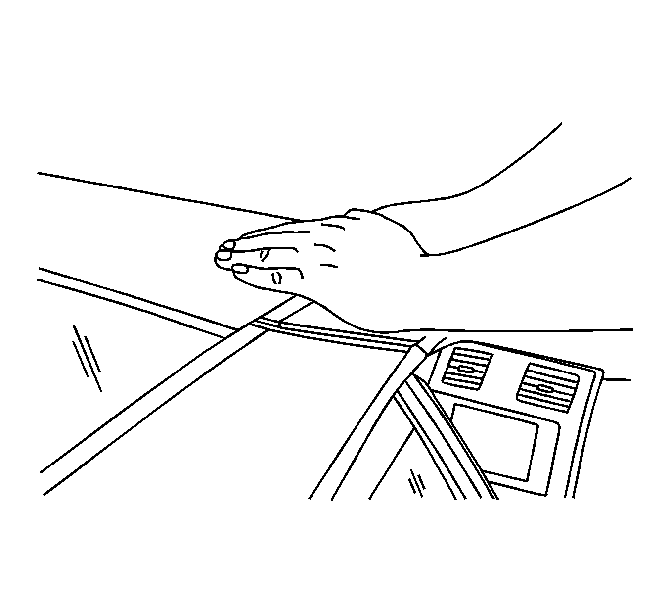
- Place your hands on the folding top and guide the top into the closed position.
- While sitting in the driver seat, pull down on the rear of the front folding top panel.
- While holding the rear of the panel down, insert the wrench and turn counterclockwise until movement stops. This will ensure that the latch jaws are fully open.
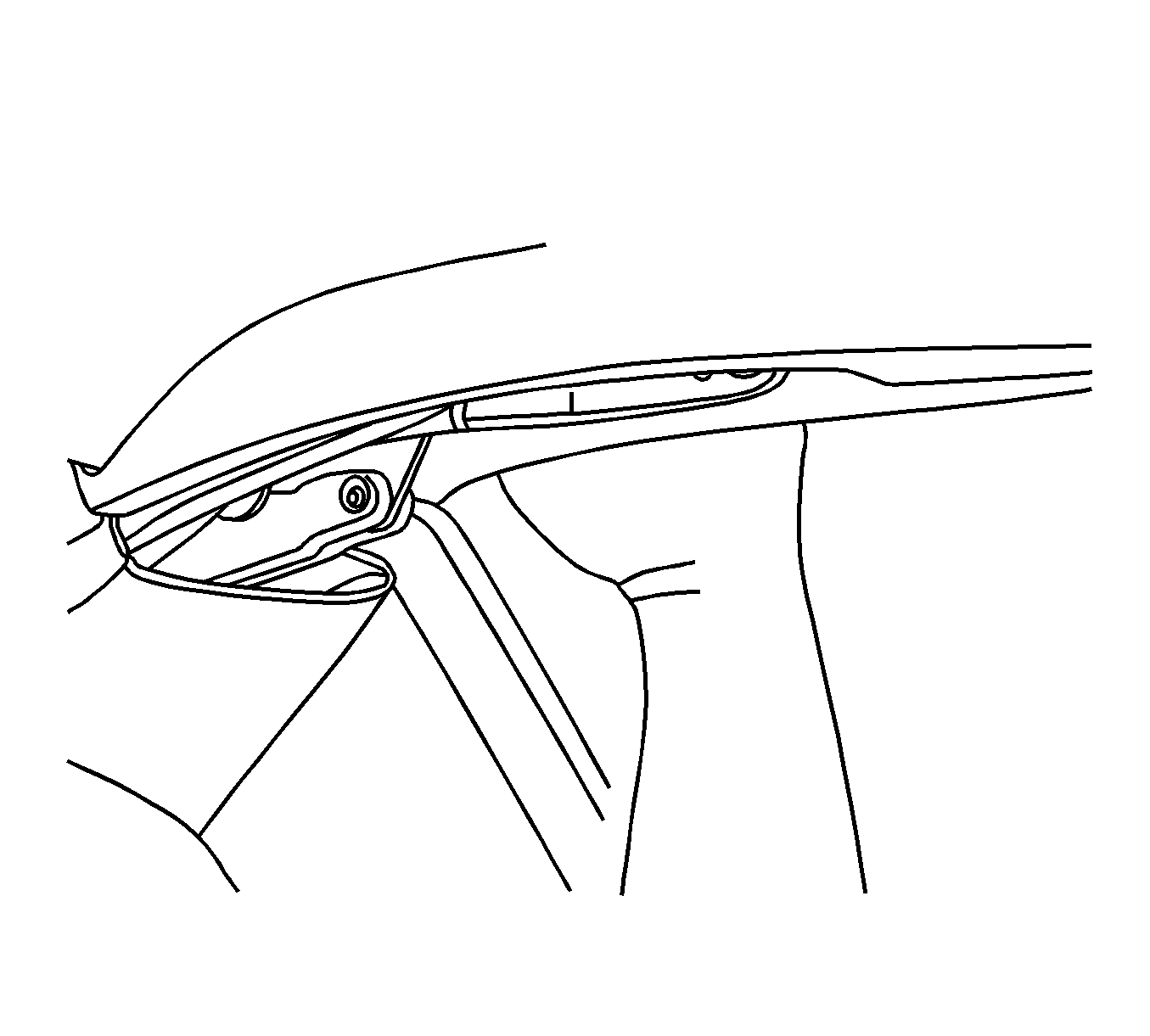
- From outside the vehicle, push down on both rear corners of the front folding top panel to ensure that the rear latches are latched.
- Before applying adhesive, dry fit the bodyside sectioned part that was removed earlier and test for proper fit and alignment.
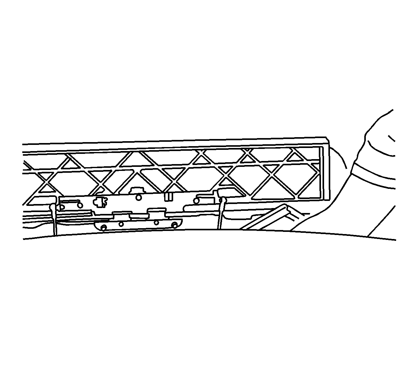
- In order to bond the bodyside-sectioned part to the vehicle, you will need to create 4 SMC backing plates, which can be made from the original rear compartment frames. Use one plate of each size for each side of the vehicle. Trim the plates as necessary to fit behind the joint.
- Clean and prepare all bonding mating surfaces according to the adhesive manufacturer's recommendations.
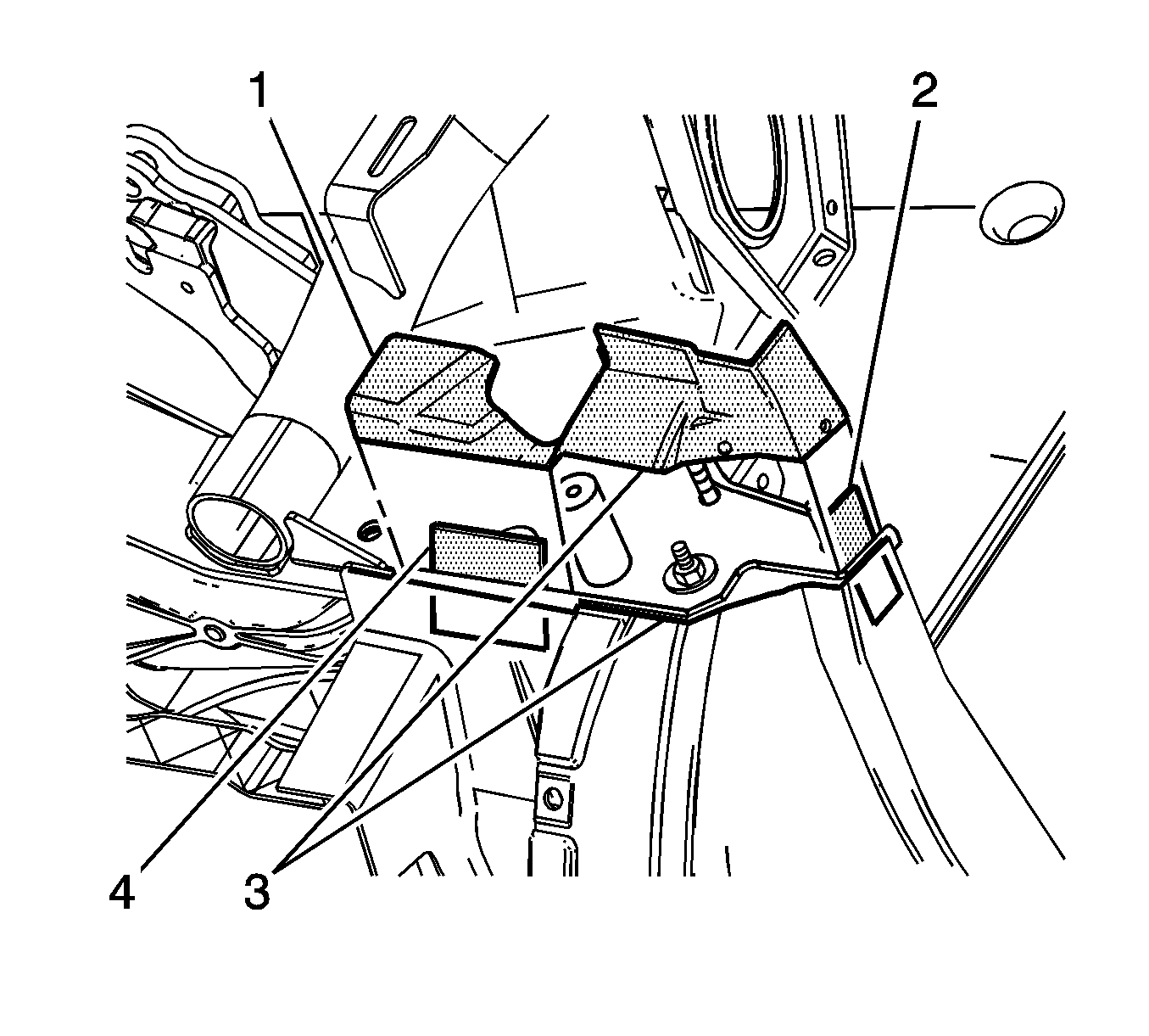
- Apply a consistent bead of structural adhesive to the bonding mating surfaces on the backing plates (1,2) and on the vehicle (3). Refer to Sheet Molded Compound (SMC) Panel Bonding in Collision Repair.
- Clamp the backing plates in place and allow to dry according to the adhesive manufacturer's recommendations.
- Remove excess adhesive.
- Temporarily install the bodyside-sectioned part (1) that was removed earlier and test for proper fit and alignment.
- Remove the bodyside sectioned part (1).
- Apply a consistent bead of structural adhesive to the bonding mating surfaces of the backing plates (2,4) and to both sides of the section joint (3). Refer to Sheet Molded Compound (SMC) Panel Bonding in Collision Repair.
- Clamp in place and allow to dry according to the adhesive manufacturer's recommendations.
- Remove the excess adhesive.
- Install both of the rear compartment frames. Refer to Rear Compartment Panel Frame Replacement in Collision Repair.
- Install both of the quarter panels. Refer to Rear Quarter Panel Replacement in Body Rear End.
- If the vehicle is equipped with a digital radio install the digital radio receiver. Refer to Digital Radio Receiver Replacement in Entertainment.
- Install the ignition lock key transmitter antennas. Refer to Ignition Lock Key Transmitter Antenna Replacement - Left Side and to Ignition Lock Key Transmitter Antenna Replacement - Right Side in Entertainment.
- Install the right side seat belt retractor. Refer to Seat Belt Retractor Replacement - Right Front in Seat Belts.
- Install the left side seat belt retractor. Refer to Seat Belt Retractor Replacement - Left Front in Seat Belts.
- Install the release actuator from the fuel filler door. Refer to Fuel Tank Filler Door Lock Actuator Replacement in Body Rear End.
- Install the right side compartment side trim. Refer to Rear Compartment Side Trim Replacement - Right Side in Body Rear End.
- Install the left side compartment side trim. Refer to Rear Compartment Side Trim Replacement - Left Side in Body Rear End.
- Connect the battery. Refer to Battery Negative Cable Disconnection and Connection in Engine Electrical.
- Verify that the folding top panels are aligned properly. Refer to Folding Top Clearance Gap Specifications .
- Operate the folding top under power through a complete cycle in both directions.
- Inspect the folding top for proper operation. Refer to Power Folding Top Description and Operation .
Notice: Refer to Fastener Notice in the Preface section.
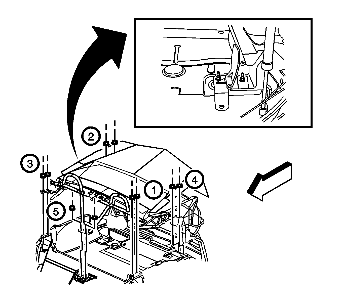
Tighten
Tighten the nuts in the designated sequence to 24 N·m (18 lb ft).

Tighten
Tighten the bolt to 20 N·m (15 lb ft).
Important: When cutting the tie wraps, protect the hydraulic lines and the electrical wires.

Tighten
Tighten the bolts to 18 N·m (13 lb ft).


Tighten
Tighten the bolts to 3 N·m (27 lb in).
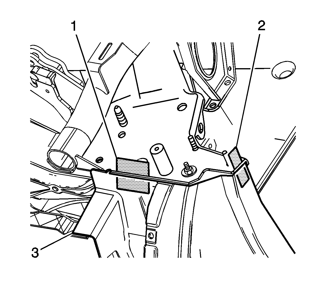
| • | Make 2 backing plates with dimensions of 30x50 mm (1 3/16x2 in). |
| • | Make 2 backing plates with dimensions of 25x50 mm (1x2 in). |
