Rear Crossmember Bolt Replacement Forward Bolt
Removal Procedure
- Remove all related panels and components.
- Remove the rear floor trim plate. Refer to Rear Floor Trim Plate Replacement .
- Locate the scribed marks labeled XMBR BOLT (1) in the floor of the rear compartment panel which identifies the area directly over the bolt.
- Drill an access hole with a 50 mm (2 in) hole saw (1).
- Remove the nut (3) using hand tools.
- Remove the spring clip (1).
- Remove the bolt (2).
Caution: To avoid personal injury when exposed to welding flashes or to galvanized (Zinc Oxide) metal toxic fumes while grinding/cutting on any type of metal or sheet molded compound, you must work in a properly ventilated area, wearing an approved respirator, eye protection , earplugs, welding gloves, and protective clothing.
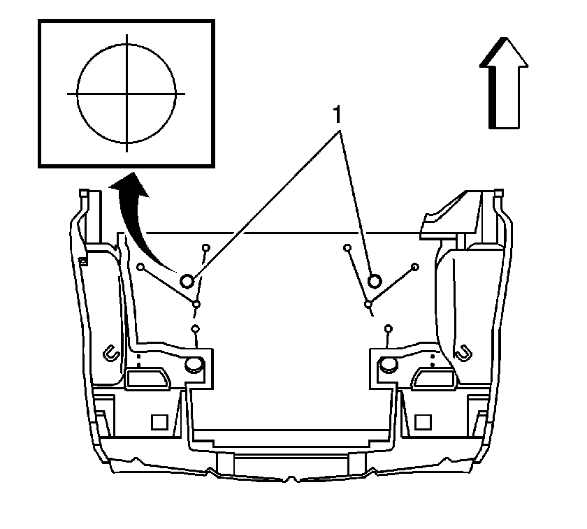
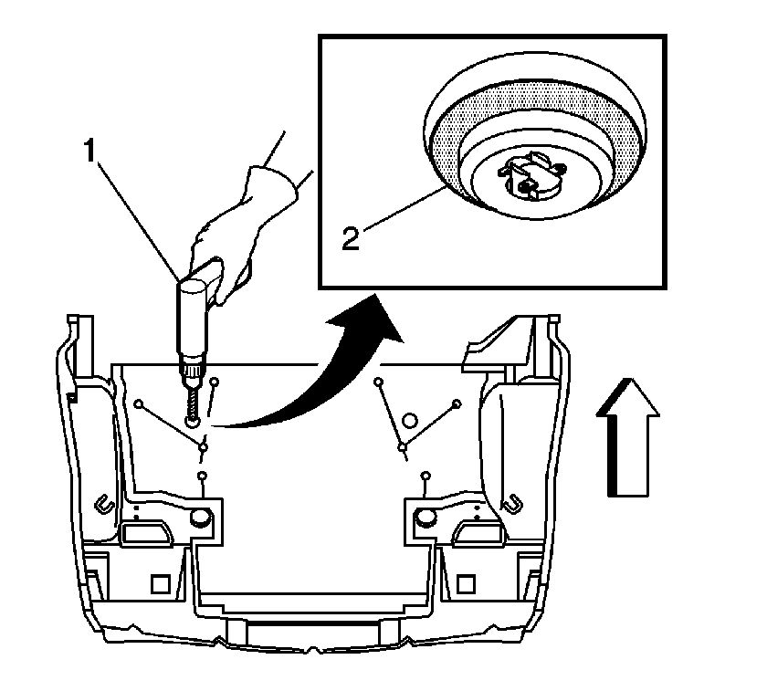
Important: Fuel system components lie under the floor of the rear compartment panel. When drilling the access hole restrict the drilling depth to 12 mm (1/2 in) (2).
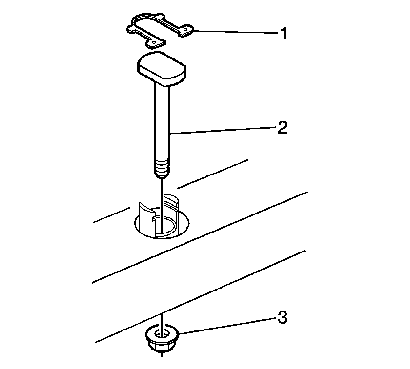
Important: Using air tools to remove the nut may damage the bolt through tube.
Installation Procedure
- Install the bolt (2).
- Install the spring clip (1).
- Install a new nut (3) and tighten with hand tools.
- Scuff all bonding surfaces.
- Clean all bonding surfaces with a lint-free rag using a naphtha solvent.
- Apply adhesive (2) GM P/N 89020330 (Canadian P/N 8902332) as necessary to seal the balsa wood.
- Cut a piece of Sheet Molded Compound (SMC) or galvanized steel (1) to cover the hole in the floor with at least a 25 mm (1 in) overlap on all sides.
- Apply a 6 mm (1/4 in) bead of adhesive (2) GM P/N 89020330 (Canadian P/N 8902332) around the perimeter of the cover.
- Position the cover over the hole in the floor (1) and press firmly into place.
- Smooth out the adhesive around the cover.
- Verify that no skips or gaps occur in the adhesive.
- Allow adhesive to cure according to adhesive manufacturer's recommendations.
- Install all related panels and components.
- Install the rear floor trim panel. Refer to Rear Floor Trim Plate Replacement .

Important: Verify that you have selected a bolt of the proper length.
Notice: Refer to Fastener Notice in the Preface section.
Important: Using air tools to install the nut may damage the bolt through tube.
Tighten
Tighten the nut to 110 N·m (81 lb in).
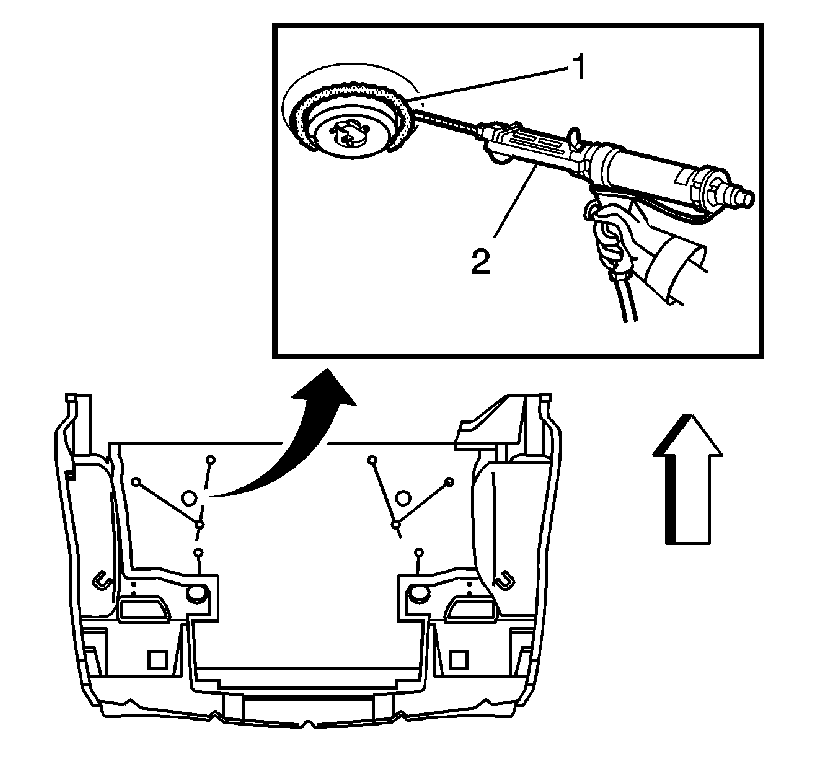
Important: Balsa wood (1) is sandwiched in between the floor. Balsa wood will rot when wet complete sealing of the balsa wood is necessary.
Important: Bonding surfaces must be dry before applying adhesive.
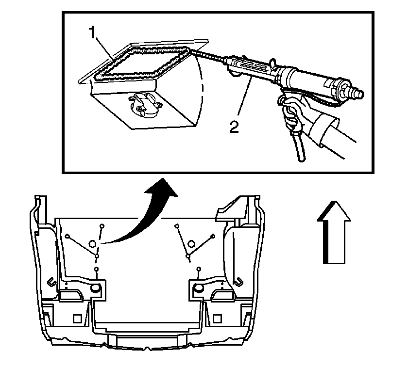
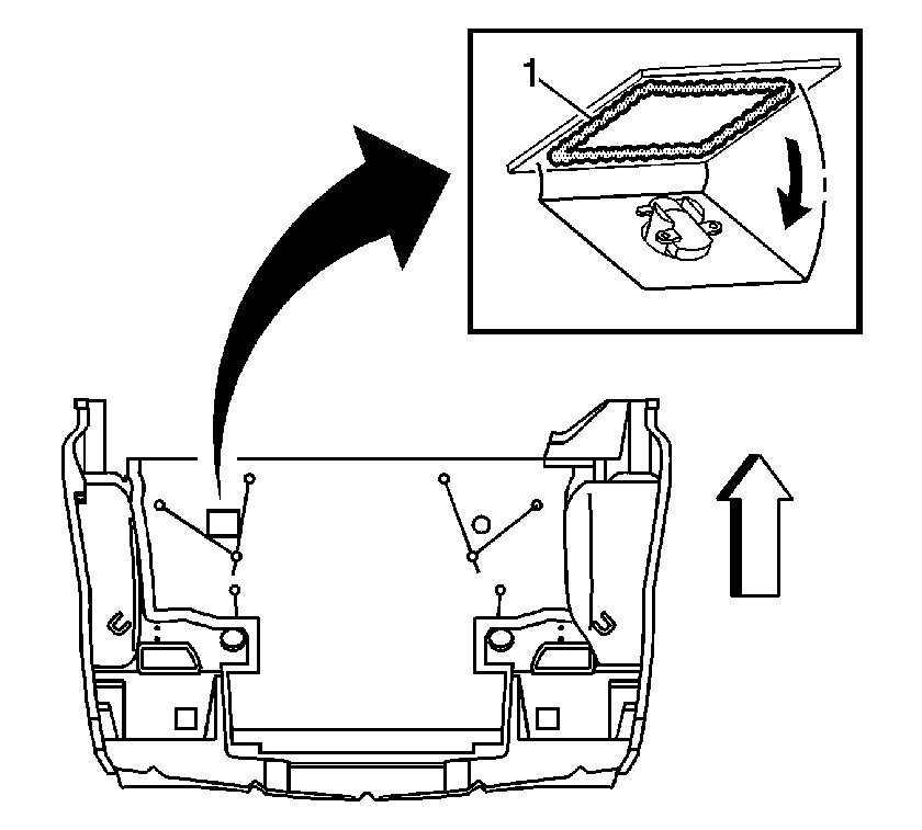
Important: Fuel system components lie under the floor of the rear compartment panel. Do not use rivets or screws to attach the cover to the floor.
Important: A leak proof seal is necessary so that exhaust and fuel fumes cannot enter the vehicle.
Rear Crossmember Bolt Replacement Rearward Bolt
Removal Procedure
- Remove all related panels and components.
- Remove the rear floor trim panel. Refer to Rear Floor Trim Plate Replacement .
- Locate the raised area (1) over the rear bolt.
- Cut (2) out an access hole over the bolt.
- Save the cut-out piece to patch the hole.
- Use hand tools to remove the nut (3).
- Remove the spring clip (1).
- Remove the bolt (2).
Caution: To avoid personal injury when exposed to welding flashes or to galvanized (Zinc Oxide) metal toxic fumes while grinding/cutting on any type of metal or sheet molded compound, you must work in a properly ventilated area, wearing an approved respirator, eye protection , earplugs, welding gloves, and protective clothing.
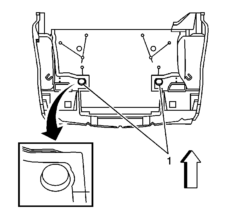
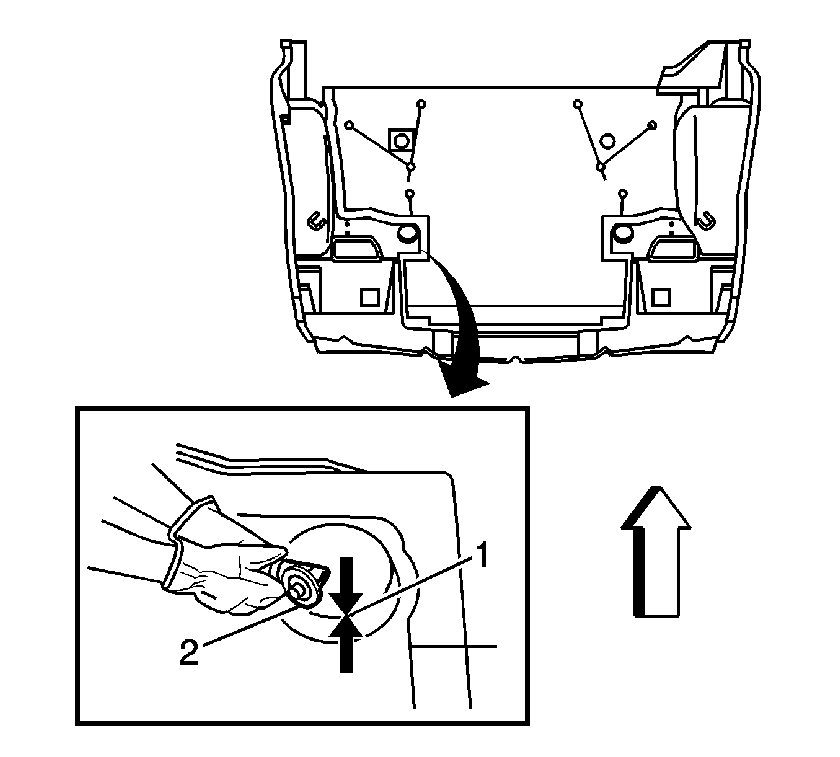
Important: Cut on a 45 degree angle (1) or less to aid in using the piece for a patch.

Important: Using air tools to remove the nut may damage the bolt through tube.
Installation Procedure
- Install the bolt (2).
- Install the spring clip (1).
- Install a new nut (3) and tighten with hand tools.
- Scuff all bonding surfaces.
- Clean all bonding surfaces with a lint-free rag using a naphtha solvent.
- Apply adhesive bonding material (1) GM P/N 89020330 (Canadian P/N 8902332) as necessary to the repair area of the floor and the patch.
- Position the patch (1) and press firmly into place.
- Smooth out the adhesive around the repaired area.
- Verify that no skips or gaps occur in the adhesive.
- Allow adhesive to cure according to adhesive manufacturer's recommendations.
- Install all related panels and components.
- Install the rear floor trim panel. Refer to Rear Floor Trim Plate Replacement .

Important: Verify that you have selected a bolt of the proper length.
Notice: Refer to Fastener Notice in the Preface section.
Important: Using air tools to remove the nut may damage the bolt through tube.
Tighten
Tighten the nut to 110 N·m (81 lb ft).
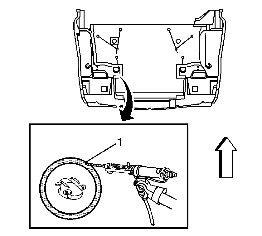
Important: Use the original cut-out piece to patch the hole
Important: Bonding surfaces must be dry before applying adhesive.
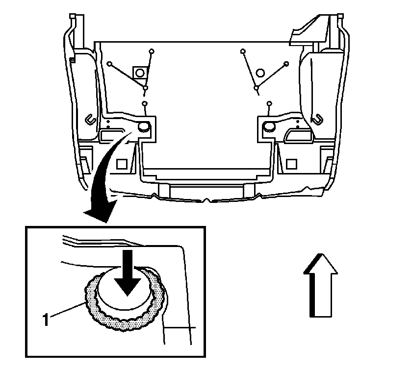
Important: A leak proof seal is necessary so that exhaust and fuel fumes cannot enter the vehicle.
