For 1990-2009 cars only
Special Tools
J 28467-81 Engine Support Fixture Kit
Installation Procedure
- Remove the hood. Refer to Hood Replacement.
- Remove the engine cover. Refer to Intake Manifold Sight Shield Replacement.
- Disconnect the negative battery cable from the battery. Refer to Battery Negative Cable Disconnection and Connection.
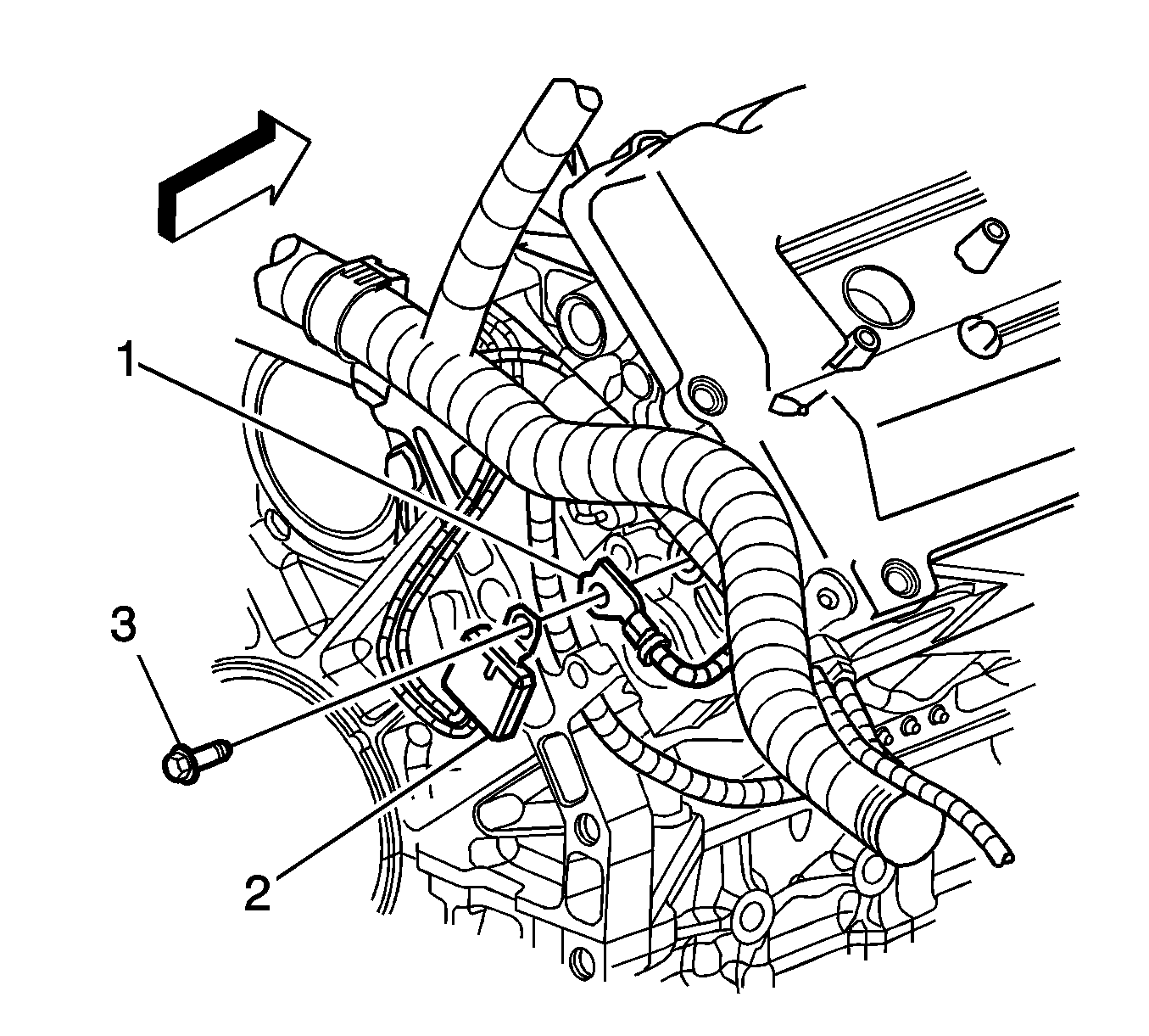
- Remove the battery negative cable bolt (3) from the RH rear of cylinder head. Position the battery negative cable (1) and ground junction (2) aside.
- Remove the camshaft cover ground strap from the camshaft cover. Position the ground strap aside.
- Remove the plastic wire harness protector from the frame rail pinch weld to provide clearance for the engine lift hook.
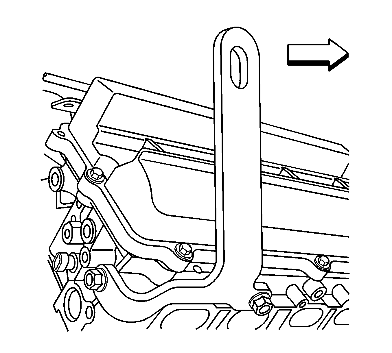
- Install the J 28467-87 Right Engine Lift Bracket to the right cylinder head.
- Remove the bolt securing the wiring harness to the left cylinder head.
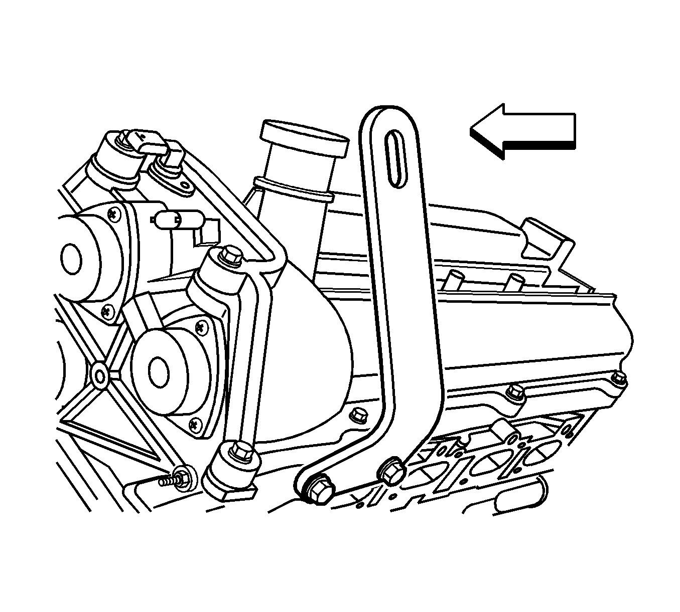
- Install the J 28467-86 Left Engine Lift Bracket to the left cylinder head.
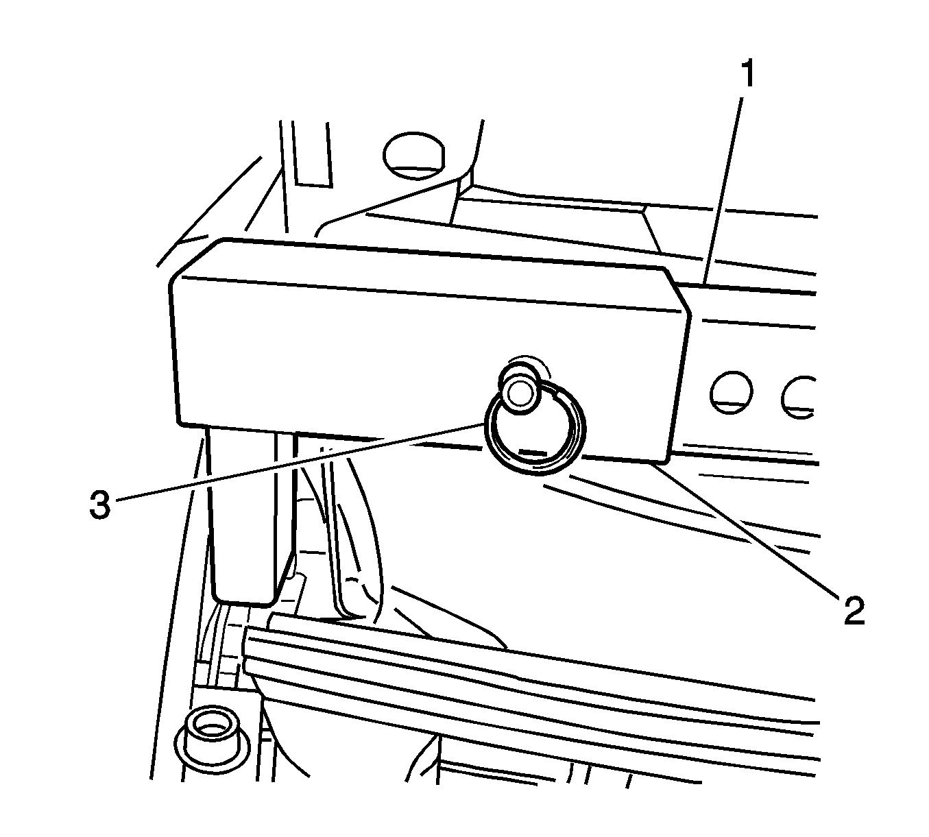
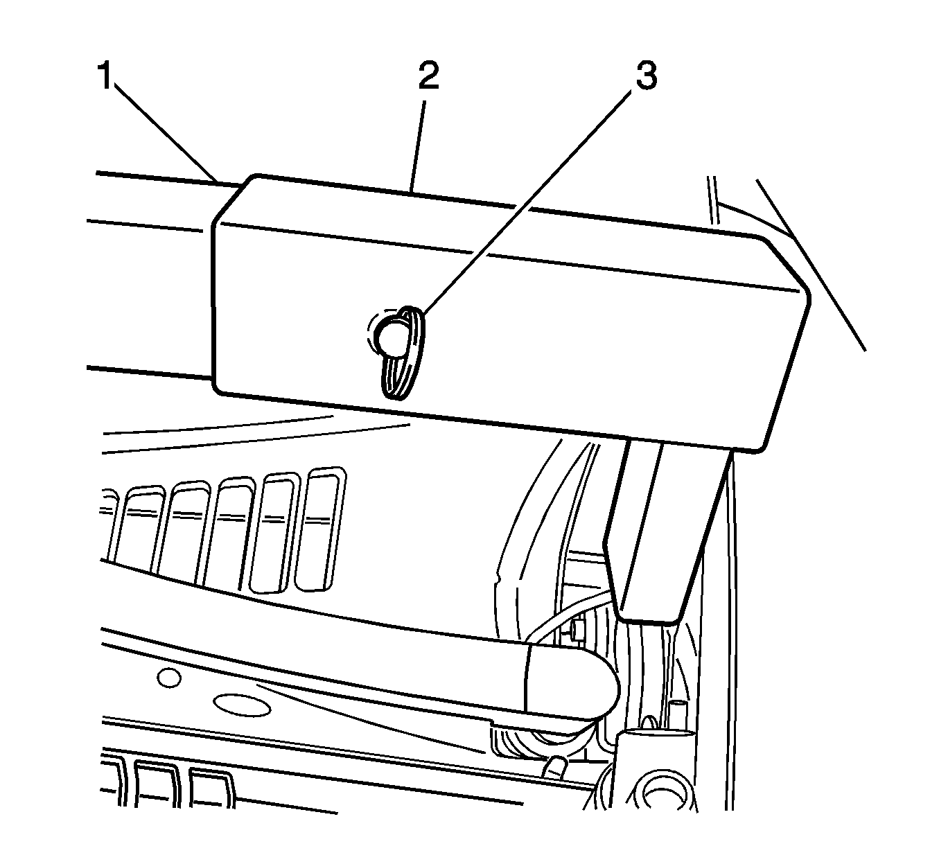
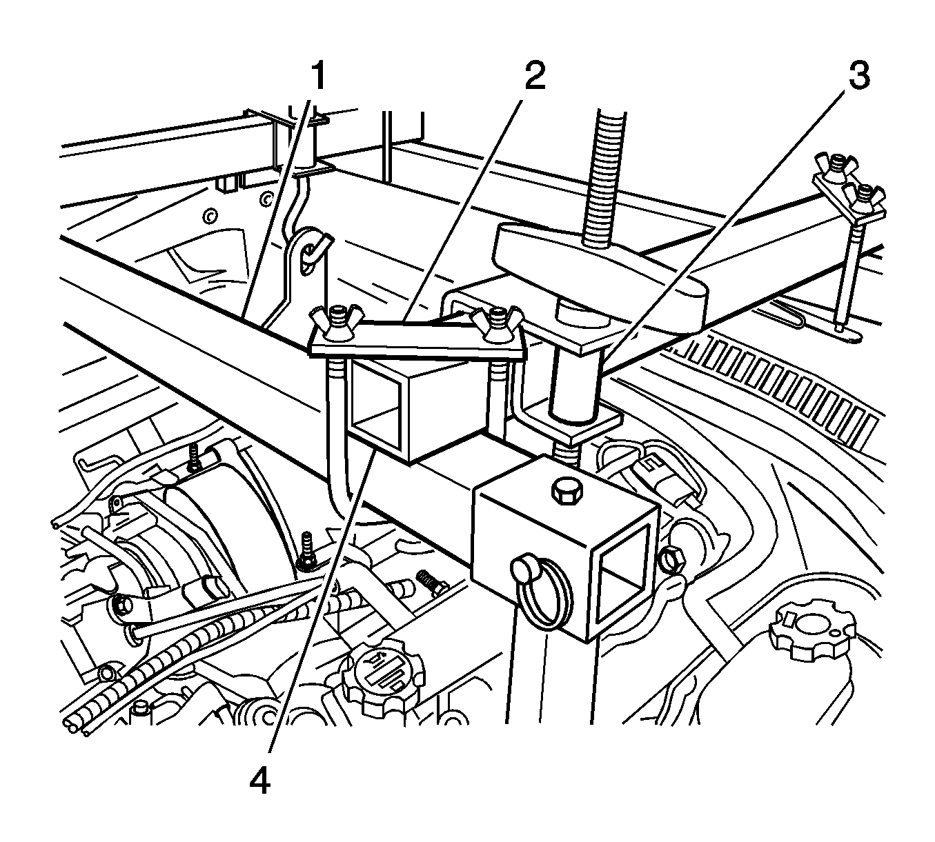
- Assemble a J 28467-83 Rear Crossbar Support (2) to each end of the J 28467-3 Rear Crossbar (1). Secure the assembly with the lock pin (3).
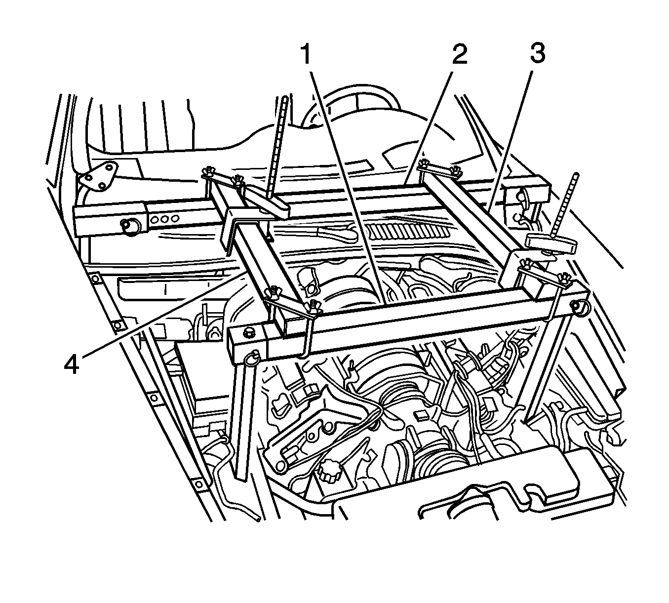
- Position the rear crossbar assembly (1-3) over the hood hinge brackets with the support located over each hood safety catch bracket.
- Assemble a J 28467-82 Front Crossbar Legs to each end of the J 28467-85 Front Crossbar (1).
- Install the 0.5 in X 2.5 in J 28467-10 Quick Release Pins (4).
- Place the front crossbar assembly with supporting legs on the right and left frame rails. Each leg should rest in the shock absorber upper mount on the frame rail.
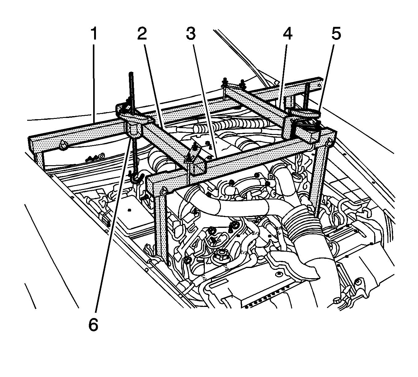
- Install the right and left sidebars (3-4) over the front and rear crossbars.
- Install the J 28467-1A assembly and hand tighten.
- Repeat steps 12 and 13 for the remaining three corners of the support fixture assembly.
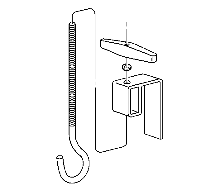
- Install the J 28467-7A lift hook through the J 28467-6A lift hook bracket.
- Install the ½ inch lift hook washer and the J 28467-34 lift hook wing nut onto the J 28467-7A lift hook.
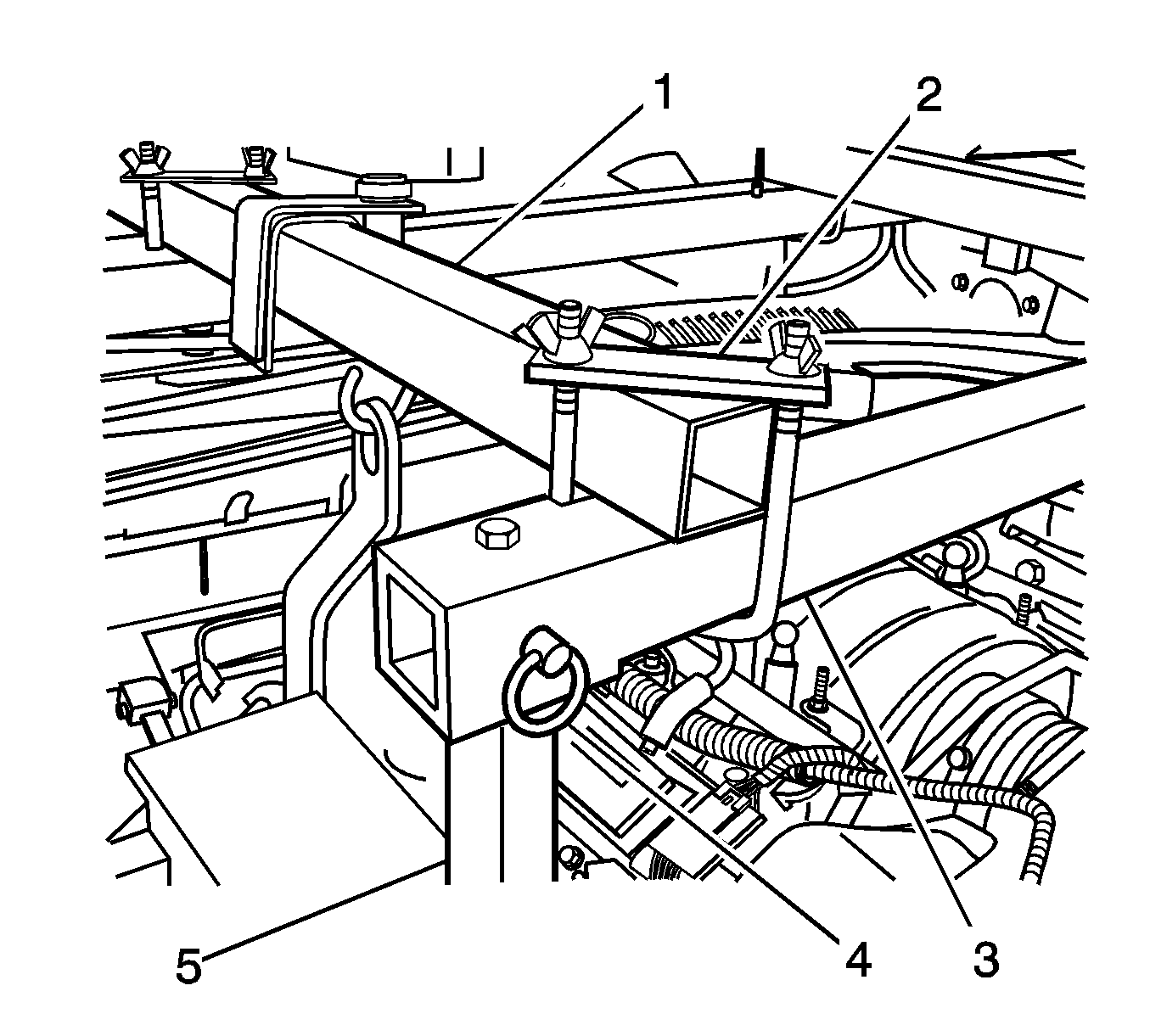
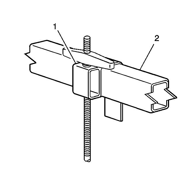
- Install the J 28467-6A assembled lift hook (1) over the J 28467-84 left sidebar (2).
- Adjust the J 28467-6A assembled lift hook bracket (1) in order to align the hook with the J 28467-86 left engine lift hook bracket.
- Repeat step 18 for the right lift hook (3).
- Install each J 28467-7A lift hook (5,6) through each engine lift hook bracket. Ensure that the hooks do not damage the surrounding components.
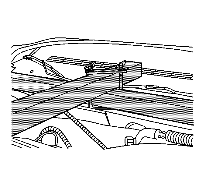
- Hand-tighten the lift hook wing nuts securely to remove all slack from the engine support fixture assembly.

Removal Procedure
- Loosen and remove the J 28467-7A lift hooks (5,6)
- Remove the J 28467-81 Engine Support Fixture Kit (1-4).
- Remove the J 28467-86 Left Engine Lift Bracket from the left cylinder head.
- Install the bolt securing the wiring harness to the left cylinder head and tighten to 35 N·m (26 lb ft).
- Remove the J 28467-87 Right Engine Lift Bracket from the right cylinder head.
- Install the plastic wire harness protector to the frame rail pinch weld.
- Install the camshaft cover ground strap to the camshaft cover and tighten to 10 N·m (89 lb in).
- Install the battery negative cable and ground junction to the RH rear of cylinder head and tighten to 35 N·m (26 lb ft).
- Connect the negative battery cable to the battery. Refer to Battery Negative Cable Disconnection and Connection.
- Install the engine cover. Refer to Intake Manifold Sight Shield Replacement.
- Install the hood. Refer to Hood Replacement.


Caution: Refer to Fastener Caution in the Preface section.

