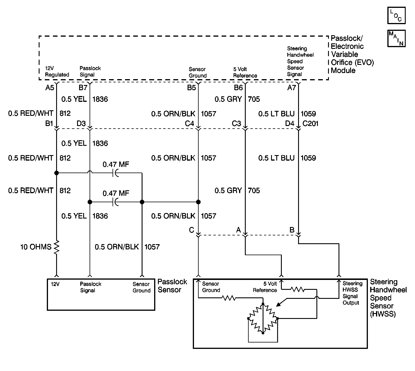
Circuit Description
The electronic variable orifice (EVO)/Passlock™ module supplies a 5.0 volt reference and a ground circuit to the steering handwheel speed (HWSS) sensor. The HWSS returns a voltage signal to the EVO/Passlock™ module. The voltage signal indicates the steering wheel rate of steer. When the steering wheel is turns one quarter revolution (90 degrees) the HWSS returns a voltage of 0.2--4.9 volts. The EVO/Passlock™ module monitors the HWSS signal voltage in order to control a percentage duty cycle (PWM) current to the steering assist control solenoid.
Conditions for Setting the DTC
| • | The HWSS signal circuit voltage is less than 0.2 volts. |
| • | The voltage condition must be met for 1 second. |
Action Taken When the DTC Sets
The EVO/Passlock™ module will not send any current to the steering assist control solenoid. This will cause the solenoid valve to retract. The retraction will provide the maximum fluid flow and the full power steering assist at all times.
Conditions for Clearing the MIL/DTC
| • | A history DTC will clear after 100 consecutive ignition cycles have occurred without the fault reoccurring. |
| • | Use the scan tool in order to clear the history and the current DTC(s). |
Diagnostic Aids
The scan tool will read the steering wheel position in volts. The voltage reading should be 0.2--4.9 volts when the following conditions exist:
| • | The ignition switch is in the ON position. |
| • | The HWSS rotates. |
Turning the wheel one quarter revolution (90 degrees) in either direction will increase the voltage at a steady rate up to 4.9 volts.
Test Description
The number(s) below refer to the step number(s) on the diagnostic table.
-
This step will prompt the technician to complete some basic checks and store the snapshot data. This creates an electronic copy of the data that is taken when the fault occurs. The information stored in the scan tool can be referred to later. Step 2 verifies when the voltage is 0.2--4.9 volts. The EVO/Passlock™ module uses the voltage in order to detect changes in the rate of steering. The system voltage should increase and decrease proportionately to the steering wheel rotational speed. If the voltage is not within the specifications, an appropriate DTC will set. Check for binding, grinding, or a damaged HWSS. Refer to Steering Wheel Position Sensor or Steering Shaft Lower Bearing Replacement .
-
This step simulates a high voltage signal. The high voltage signal will identify an open in the signal circuit.
-
This step checks for voltage with the J 39200 digital multimeter (DMM) while probing the HWSS signal circuit. The HWSS signal circuit shorts to ground if voltage is present.
-
This step checks the terminals for improper mating, broken locks, and physical damage to the wiring harness before replacement of the EVO/Passlock™ module.
Step | Action | Value(s) | Yes | No |
|---|---|---|---|---|
1 | Did you perform the Diagnostic System Check? | -- | Go to Step 2 | |
Did the HWSS value increase and decrease steadily to the specified value when rotating the steering wheel? | 0.2--4.9 volts | Go to Step 3 | ||
3 |
Is the HWSS voltage less than the specified value? | 0.2 volts | Go to Step 4 | Go to Step 13 |
4 |
Is the HWSS voltage within the specified range? | 0.2--4.9 volts | Go to Step 12 | Go to Step 5 |
Is the HWSS voltage within the specified range? | 0.2--4.9 volts | Go to Step 6 | Go to Step 10 | |
6 |
Is the HWSS voltage within the specified range? | 0.2--4.9 volts | Go to Step 8 | Go to Step 7 |
Repair the sensor return CKT 1057 (ORN/BLK) for an open to short to ground. Is the repair complete? | -- | Go to Step 8 | ||
8 | Repair the 5.0 volt reference circuit for an open or short to ground in the HWSS signal CKT 705 (GRY). Is the repair complete? | -- | Go to Step 9 | |
9 |
Is the repair complete? | -- | Go to Step 13 | |
10 | Test the HWSS signal CKT 1059 (LT BLU) for an open or short to ground. Is the repair complete? | -- | Go to Step 11 | |
11 | Inspect the HWSS signal CKT 1059 (LT BLU) for a poor connection at the EVO/Passlock™ module. Is the repair complete? | -- | Go to Step 12 | |
12 | Replace the HWSS. Refer to Steering Wheel Position Sensor or Steering Shaft Lower Bearing Replacement . Is the replacement complete? | -- | -- | |
13 | Replace the EVO/Passlock™ module. Refer to Elec Variable Orifice Passlock Module Replacement . Is the replacement complete? | -- | -- |
