For 1990-2009 cars only
Removal Procedure
- Remove the brake drum. Refer to Brake Drum Replacement .
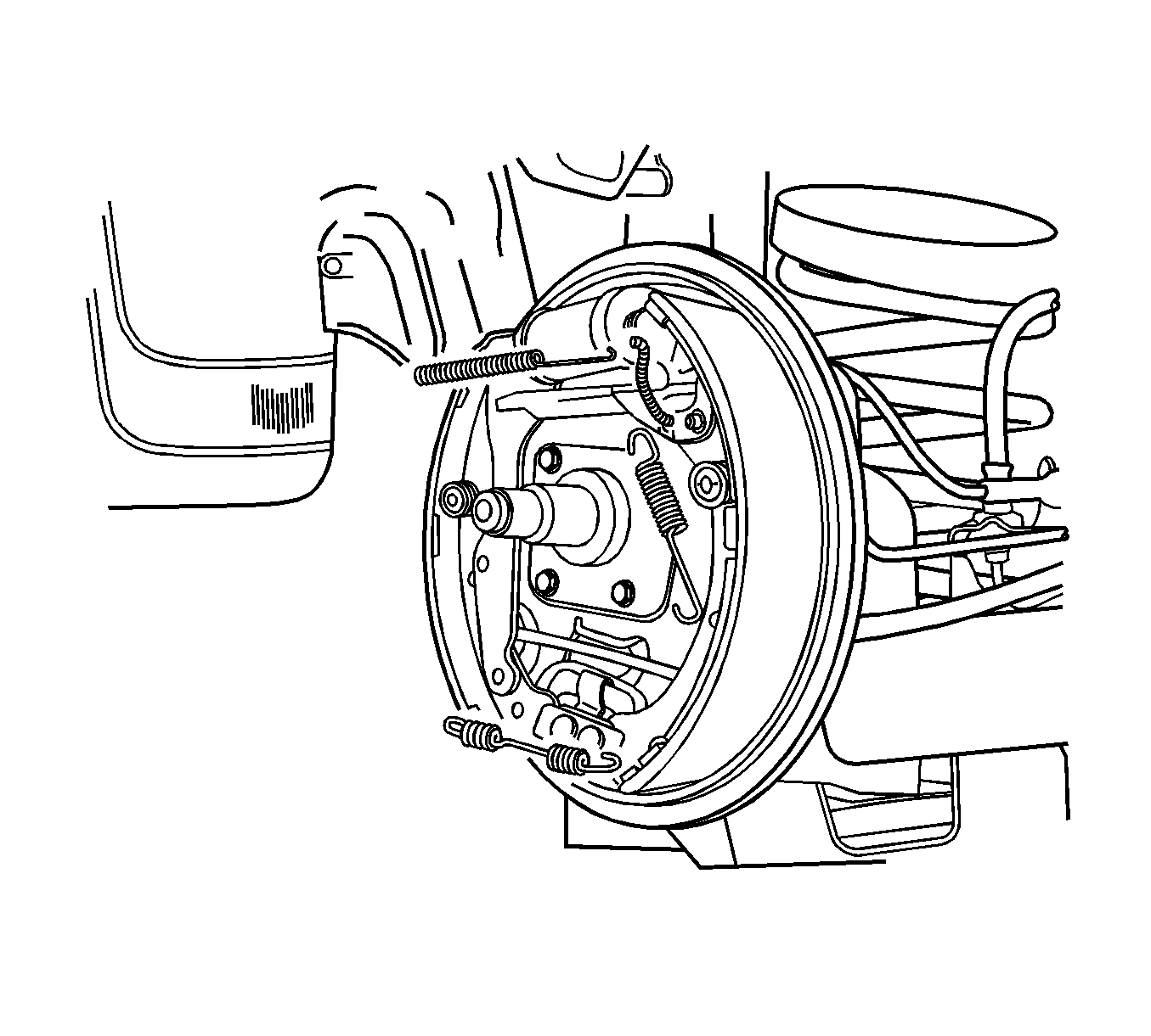
- Remove the lower return spring.
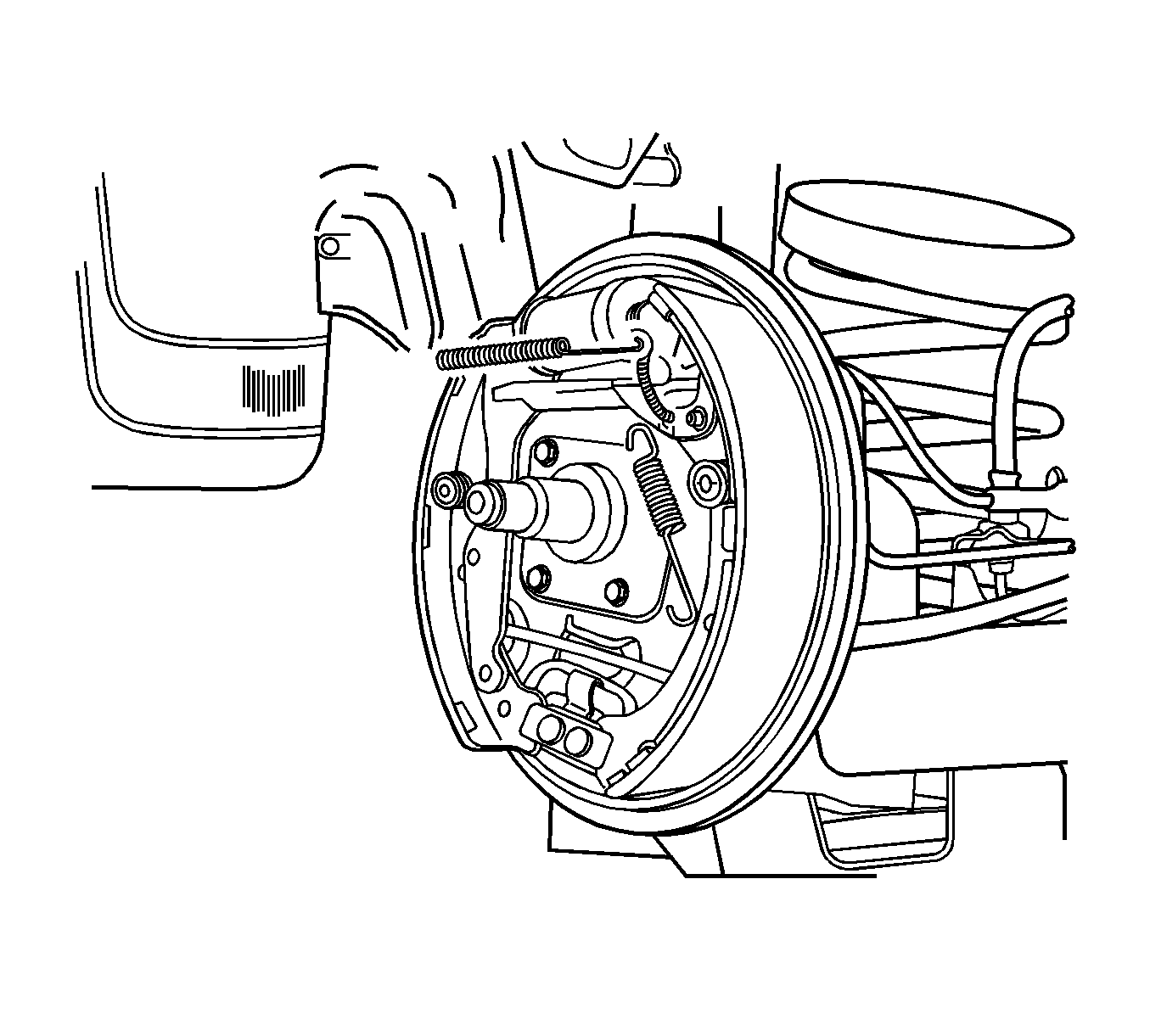
- Remove the upper end of the connecting link from the leading shoe to relieve tension on the upper return spring.
- Remove the connecting link spring.
- Remove the connecting link and the adjusting lever.
- Remove the upper return spring and the adjuster.
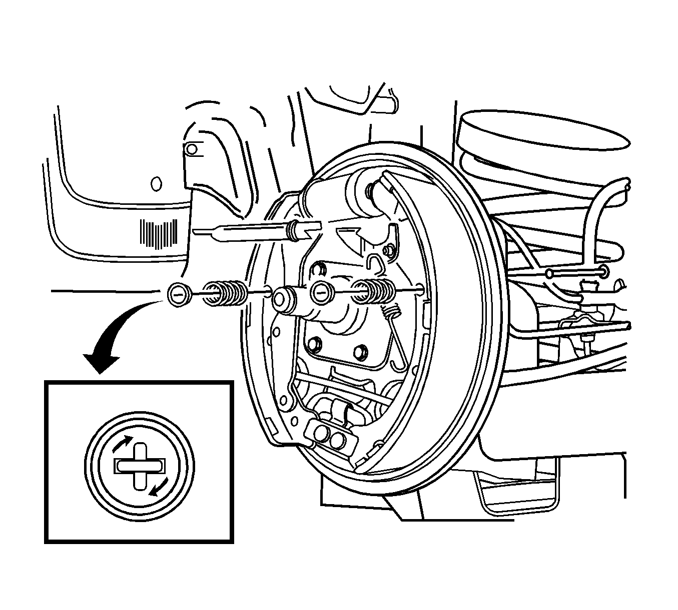
- Remove the trailing shoe hold-down spring and cap.
- Remove the trailing shoe hold-down pin.
- Remove the trailing shoe.
- Remove the leading shoe hold-down spring and cap.
- Remove the leading shoe hold-down pin.
- Remove the leading shoe.
Caution: Refer to Brake Dust Caution in the Preface section.


Inspection Procedure
- Measure the minimum brake lining thickness. Refer to Brake Shoe Inspection .
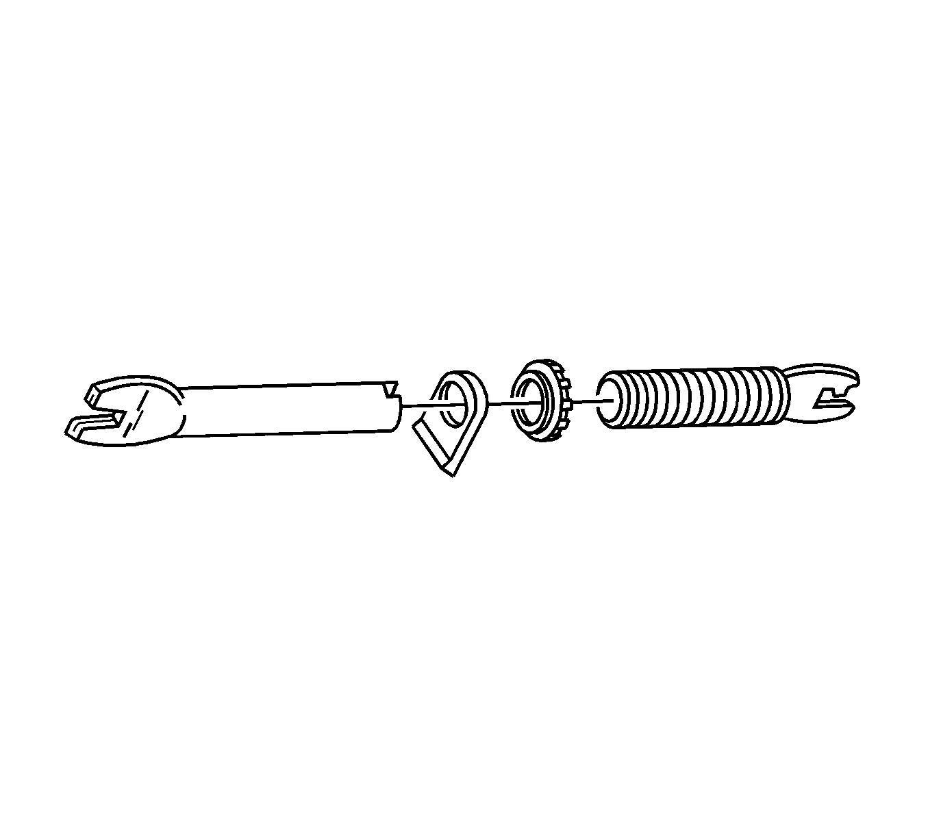
- Clean the adjuster assembly and apply grease.
- Inspect the threads of the adjuster assembly for smooth rotation.
- Inspect the brake components for damage or wear. Replace any damaged or worn components.
Caution: Refer to Safety Glasses Caution in the Preface section.

Installation Procedure
- Verify the park brake cable is properly routed.
- Attach the park brake cable to the trailing shoe lever.
- Install the trailing shoe with the hold-down spring, the cap, and the pin.
- Install the lower return spring to the trailing shoe.
- Position the leading shoe and the adjuster assembly against the backing plate.
- Install the lower return spring to the leading shoe.
- Install the adjuster assembly.
- Turn the adjuster in as far as possible.
- Install the leading shoe with the hold-down spring, the cap, and the pin.
- Install the adjusting lever to the leading shoe.
- Install the connecting link to the leading shoe.
- Install the connecting link spring.
- Install the upper return spring from the leading shoe to the connecting link.
- Ensure the adjuster assembly nut is drawn all the way to the stop.
- Adjust the rear brakes. Refer to Drum Brake Adjustment .
- Install the brake drum. Refer to Brake Drum Replacement .
- Adjust the park brake. Refer to Park Brake Adjustment .


Important: Do not overstretch the lower return spring.
Important: Do not overstretch the upper return spring.
Important: The nut must not lock firmly at the end of the adjustment assembly.
