Tools Required
J 41427 Engine Lift
Bracket
Removal Procedure
Notice: If the engine is damaged internally and a new engine assembly is installed
in the vehicle, ensure that all foreign material is flushed out of the cooling
system. You must also flush out the oil cooler system. Failure to rid the
oil cooler system of debris can result in engine damage.
- Disconnect the battery negative cable. Refer to
Battery Replacement
in Engine Electrical.
- Remove the hood. Refer to
Hood Replacement
in Body Front End.
- Raise the vehicle. Refer to
Lifting and Jacking the Vehicle
in General Information.
- Remove the underbody shields, if equipped.
- Remove the exhaust pipe from the exhaust manifolds.
Refer to
Catalytic Converter Replacement
in Engine Exhaust.
- Disconnect the engine oil cooler pipes (RWD vehicle). Refer to
Engine Oil Cooler Hose/Pipe Replacement
in Engine
Cooling.
- Disconnect the remote oil filter adapter inlet and outlet hoses
(Four Wheel Drive vehicle). Refer to
Remote Oil Filter Adapter Pipe Replacement
.
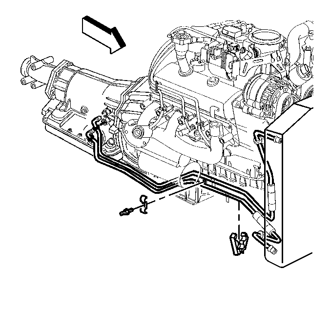
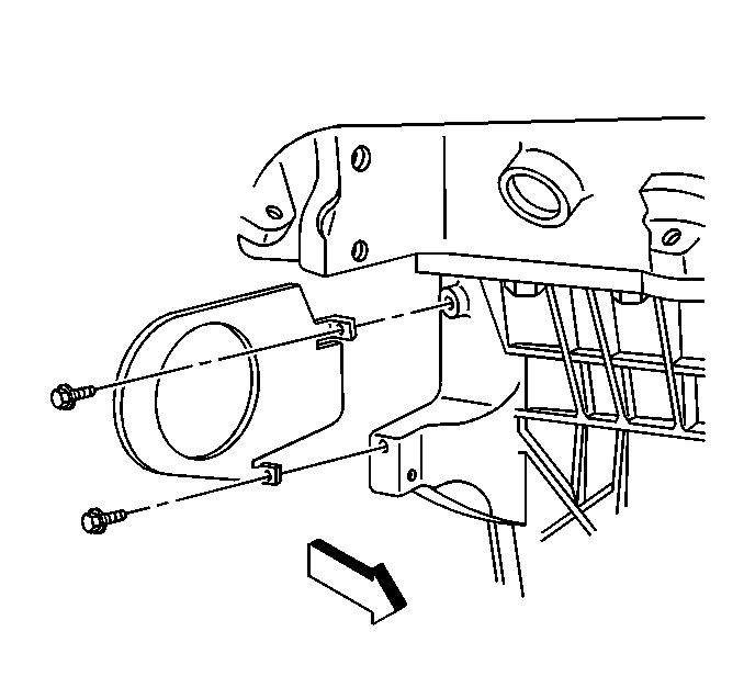
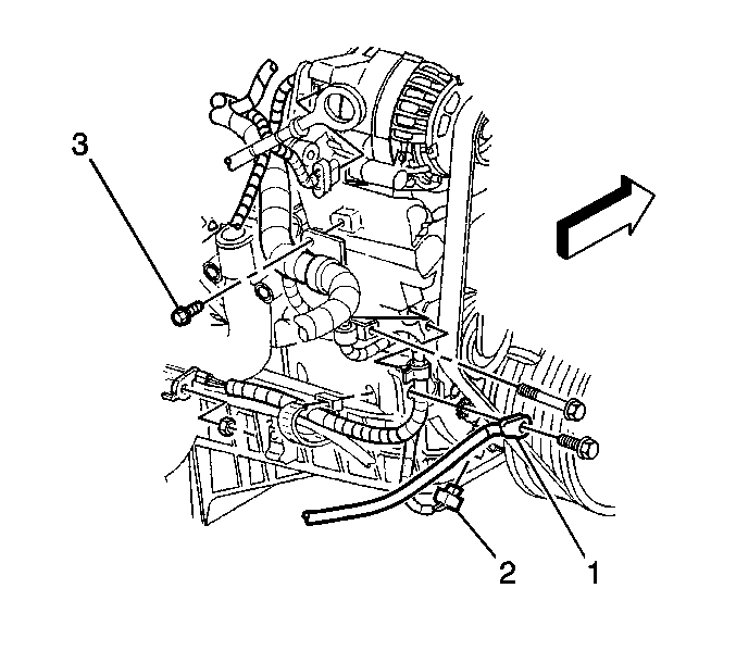
- Remove the stud holding
the starter wire harness and if equipped, transmission oil cooler lines.
- Remove the starter. Refer to
Starter Motor Replacement
in Engine Electrical.
- Remove the transmission
cover.
- Remove the transmission.
- Remove the front engine
mount through bolts.
- Lower the vehicle.
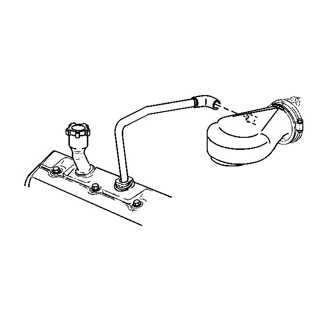
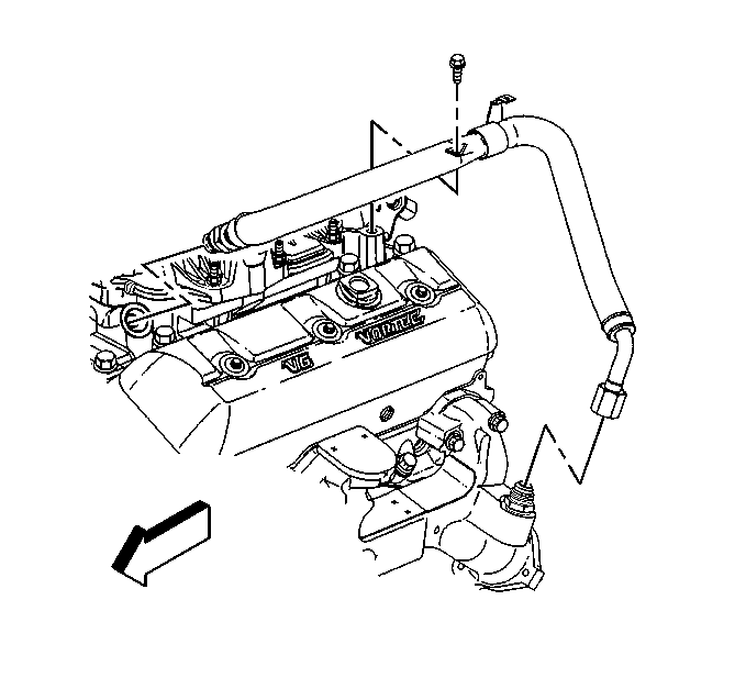
- Remove the PCV tube from
the right valve rocker arm cover and the air cleaner outlet duct.
- Remove the air cleaner outlet duct from the throttle body. Refer
to
Air Cleaner Outlet Duct Replacement
in
Engine Controls.
Caution: In order to avoid possible injury or vehicle damage, always replace
the accelerator control cable with a NEW cable whenever you remove the engine
from the vehicle.
In order to avoid cruise control cable damage, position the cable out
of the way while you remove or install the engine. Do not pry
or lean against the cruise control cable and do not kink the cable. You must
replace a damaged cable.
- Remove the accelerator control cable. Refer to
Accelerator Control Cable Replacement
in Engine
Controls.
- Remove the cruise control cable, if equipped from the throttle
shaft and the accelerator cable bracket. Refer to
Cruise Control Cable Replacement
in Cruise Control.
- Remove the radiator. Refer to
Radiator Replacement
in Engine Cooling.
- Remove the inlet and outlet radiator hoses from the engine. Refer
to
Radiator Hose Replacement
in Engine
Cooling.
- Disconnect the heater hoses from the engine. Refer to
Heater Hoses Replacement
in Heating Ventilation
and Air Conditioning.
- Disconnect the power brake
booster vacuum hose from the intake manifold.
- Disconnect the vacuum hose for the A/C system, if equipped from
the intake manifold.
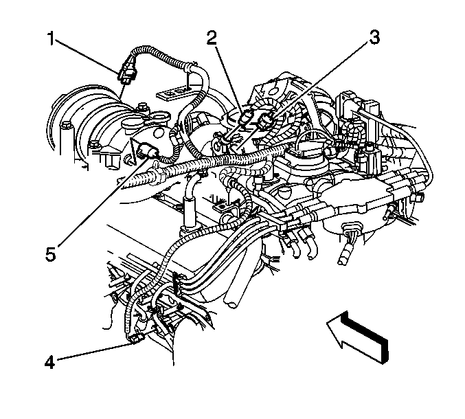
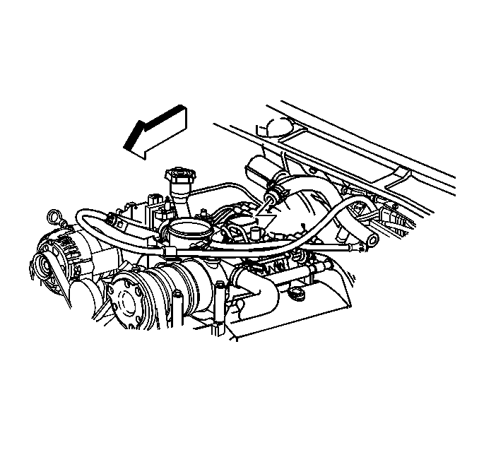
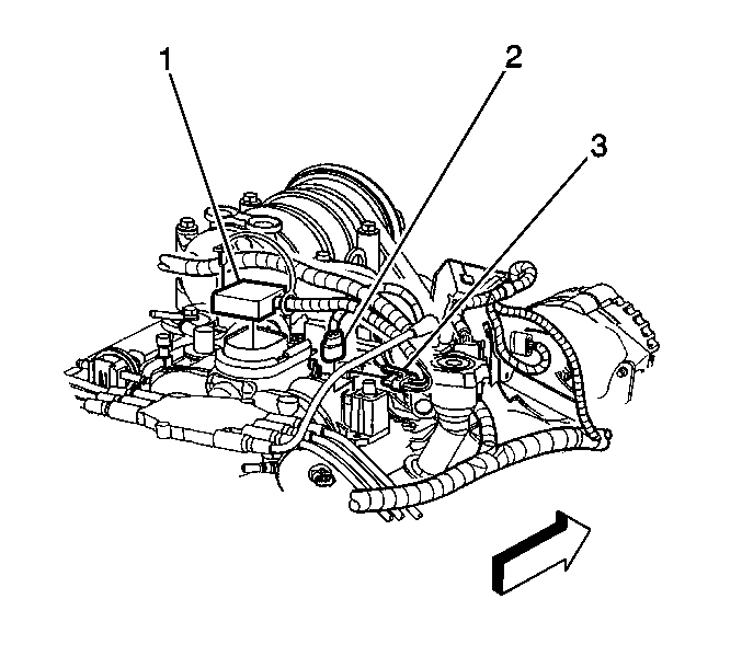
- Disconnect the following
electrical connectors:
| • | The A/C compressor clutch (1), if equipped |
| • | The A/c compressor cutoff switch (5), if equipped |
| • | The IAC valve motor (3) |
- Disconnect the following
electrical connectors:
| • | The fuel meter body (1) |
| • | The EVAP canister purge solenoid (2) |
- Disconnect the following
electrical connectors:
- Disconnect the following
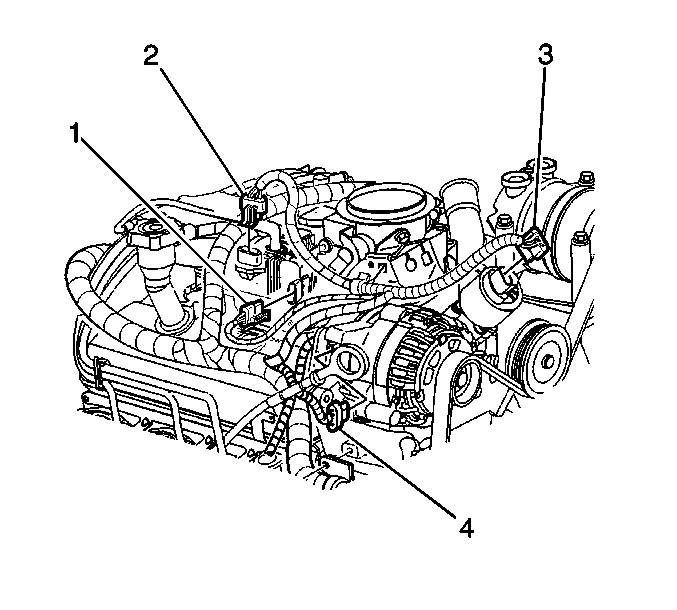
electrical connectors:
| • | The engine oil pressure sensor (2) |
- Disconnect the CKP sensor
(2) electrical connector.
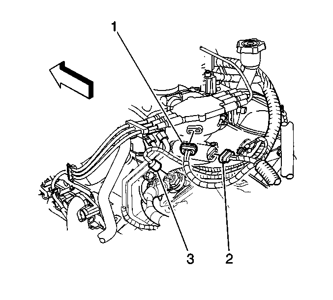
- Remove the bolt and the battery negative cable (1).
- Remove the engine wiring harness bracket bolt (3).
- Remove the engine wiring harness clips from the front of the engine.
- Remove the engine wiring harness clips from the brackets.
- Move the engine wiring harness aside.
- Remove the generator. Refer to
Generator Replacement
in Engine Electrical.
- Remove the bolt holding
the ground wires to the left cylinder head.
- Remove the bolt holding the fuel pipe bracket to the rear of left
cylinder head.
- Remove the bolts holding
the ground wires to the right cylinder head.
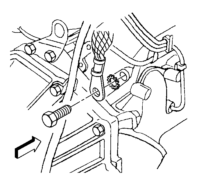
- Remove the bolt holding
the ground strap to the right cylinder head.
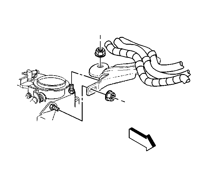
- Remove the accelerator
control cable bracket from the throttle body.
- Remove the water pump pulley. Refer to
Water Pump Replacement
in Engine Cooling.
- Remove the A/C compressor, if equipped. Refer to
Air Conditioning Compressor Replacement
in Heating Ventilation and Air Conditioning.
- Remove the nut holding the AIR reactor pipe bracket to the front of
the engine, if equipped.
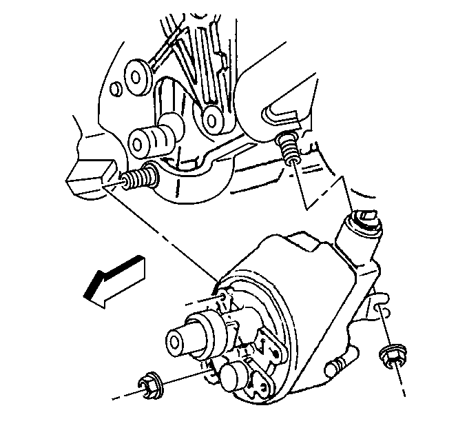
- Remove the nuts holding the power steering pump rear bracket to
the engine.
- Remove the power steering pump mounting bracket. Refer to
Accessory Mounting Brackets Replacement
.
| • | The power steering pump can remain on the mounting bracket. |
| • | The hoses do not require removal. |
| • | Remove the three bolts and the nut. |
| • | Slide the mounting bracket off of the stud. |
| • | Secure the mounting bracket out of the way. |
Notice: Remove the AIR pipes before engine removal. The AIR pipes can break
or damage easily causing erratic engine operation.
- Remove both of the secondary air injection (AIR) reactor
pipes from the engine.
- Remove the AIR shut-off valve and hoses. Refer to
Secondary Air Injection Shutoff Valve Replacement
in Engine Controls.
- Remove the distributor cap. Refer to
Distributor Replacement
in Engine Electrical.
- Disconnect the fuel pipes at the rear of the intake manifold.
Refer to
Fuel Hose/Pipes Replacement - Engine Compartment
in Engine Controls.
- Disconnect the EVAP canister purge solenoid valve pipe. Refer
to
Evaporative Emission Canister Purge Solenoid Valve Replacement
in Engine Controls.
- Remove the water outlet. Refer to
Engine Coolant Thermostat Replacement
in Engine Cooling.
- Remove the spark plug
wire harness retainer from the exhaust gas recirculation (EGR) valve inlet
pipe.
- Remove the clamp bolt for the EGR valve inlet pipe.
- Remove the EGR valve inlet pipe from the intake and the exhaust
manifolds.
Notice: Use the correct fastener in the correct location. Replacement fasteners
must be the correct part number for that application. Fasteners requiring
replacement or fasteners requiring the use of thread locking compound or sealant
are identified in the service procedure. Do not use paints, lubricants, or
corrosion inhibitors on fasteners or fastener joint surfaces unless specified.
These coatings affect fastener torque and joint clamping force and may damage
the fastener. Use the correct tightening sequence and specifications when
installing fasteners in order to avoid damage to parts and systems.
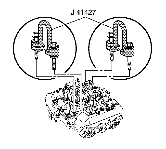
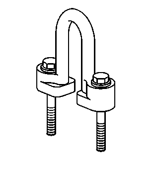
- Attach the J 41427
to the left front and the right rear intake manifold mounting bolts, using
the following procedure:
| 53.1. | Remove the right rear lower intake manifold bolts. |
| 53.2. | Install the J 41427
marked RIGHT REAR. |
| 53.3. | Install the retaining bolts. |
| 53.4. | Remove the left front lower intake manifold bolts. |
| 53.5. | Install the J 41427
marked LEFT FRONT with the arrow pointing to the front of the engine. |
| 53.6. | Install the retaining bolts. |
Tighten
Tighten the retaining bolts to 15 N·m (11 lb ft).
- Attach a suitable lifting device to the engine lift brackets.
- Remove the engine.
Installation Procedure
Notice: If the engine is damaged internally and a new engine assembly is installed
in the vehicle, ensure that all foreign material is flushed out of the cooling
system. You must also flush out the oil cooler system. Failure to rid the
oil cooler system of debris can result in engine damage.
Notice: Use the correct fastener in the correct location. Replacement fasteners
must be the correct part number for that application. Fasteners requiring
replacement or fasteners requiring the use of thread locking compound or sealant
are identified in the service procedure. Do not use paints, lubricants, or
corrosion inhibitors on fasteners or fastener joint surfaces unless specified.
These coatings affect fastener torque and joint clamping force and may damage
the fastener. Use the correct tightening sequence and specifications when
installing fasteners in order to avoid damage to parts and systems.
- Attach the J 41427
to the left front and the right rear intake manifold mounting bolts, using
the following procedure:
| 1.1. | Remove the right rear lower intake manifold bolts. |
| 1.2. | Install the J 41427
marked RIGHT REAR. |
| 1.3. | Install the retaining bolts. |
| 1.4. | Remove the left front lower intake manifold bolts. |
| 1.5. | Install the J 41427
marked LEFT FRONT with the arrow pointing to the front of the engine. |
| 1.6. | Install the retaining bolts. |
Tighten
Tighten the retaining bolts to 15 N·m (11 lb ft).
- Attach a suitable lifting device to the engine lift brackets.
- Install the engine into the vehicle.
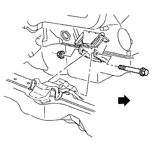
- Install the engine mount
through-bolts and nuts.
Tighten
Tighten the engine mount through-bolts or the nuts to the following:
| • | Tighten the through-bolts to 74 N·m (55 lb ft) |
| • | Tighten the nuts to 63 N·m (46 lb ft) |
- Remove the J 41427
and the engine lifting device.
- Apply thread lock GM P/N 12345382 or equivalent
to the threads of the lower intake manifold bolts.
- Install the intake manifold bolts.
Tighten
- Tighten the bolts the first pass to 3 N·m (27 lb in).
- Tighten the bolts the second pass to 12 N·m (106 lb in).
- Tighten the bolts the third pass to 15 N·m (11 lb ft).
- Install the EGR valve
inlet pipe to the intake manifold and the exhaust manifold.
Tighten
- Tighten the EGR valve inlet pipe intake manifold nut to 25 N·m
(18 lb ft).
- Tighten the EGR valve inlet pipe exhaust manifold nut to 30 N·m
(22 lb ft).
- Tighten the EGR valve inlet pipe clamp bolt 25 N·m
(18 lb ft).
- Install the spark plug wire harness retainer on the EGR valve
inlet pipe.
- Install the water outlet. Refer to
Engine Coolant Thermostat Replacement
in Engine Cooling.
- Connect the fuel pipes at the rear of the engine. Refer to
Fuel Hose/Pipes Replacement - Engine Compartment
in
Engine Controls.
- Install the distributor cap. Refer to
Distributor Replacement
in Engine Electrical.
- Connect the EVAP canister purge solenoid valve pipe. Refer to
Evaporative Emission Canister Purge Solenoid Valve Replacement
in Engine Controls.
- Install both of the AIR reactor pipes to the engine.
- Install the AIR shut-off valve and hoses. Refer to
Secondary Air Injection Shutoff Valve Replacement
in Engine Controls.
- Install the power steering pump mounting bracket. Refer to
Accessory Mounting Brackets Replacement
.
- Install the nuts holding the power steering pump rear bracket to the
engine.
Tighten
Tighten the power steering pump rear bracket nuts to 41 N·m
(30 lb ft).
- Install the nut holding the AIR reactor pipe bracket , if equipped
to the stud on the front of the engine.
Tighten
Tighten the bolt to 41 N·m (30 lb ft).
- Install the A/C compressor, if equipped. Refer to
Air Conditioning Compressor Replacement
in Heating Ventilation and Air Conditioning.
- Install the water pump pulley. Refer to
Water Pump Replacement
in Engine Cooling.
- Install the accelerator
control cable bracket to the throttle body.
Tighten
Tighten the bolt to 9 N·m (80 lb in).
- Install the bolt holding
the ground wires to the left cylinder head.
Tighten
Tighten the ground wire bolt to 35 N·m (26 lb ft).
- Install the bolt holding the fuel pipe bracket to the rear of
the left cylinder head.
Tighten
Tighten the fuel pipe bracket bolt to 30 N·m (22 lb ft).
- Install the stud holding
the ground wires to the right cylinder head.
Tighten
Tighten the ground wire stud to 35 N·m (26 lb ft).
- Install the bolt and the
ground strap to the rear of the right cylinder head.
Tighten
Tighten the ground strap bolt to 35 N·m (26 lb ft).
- Position the engine wiring
harness.
- Install the engine wiring harness clips to the brackets.
- Install the engine wiring harness clips to the front of the engine.
- Connect the CKP sensor electrical connector (2).
- Install the bolt and the battery negative cable (1).
Tighten
Tighten the bolt to 17 N·m (13 lb ft).
- Install the engine wiring harness bracket bolt (3) to the generator
mounting bracket.
Tighten
Tighten the stud to 25 N·m (18 lb ft).
- Install the generator. Refer to
Generator Replacement
in Engine Electrical.
- Connect the following
electrical connectors:
| • | The engine oil pressure sensor (2) |
- Connect the following
electrical connectors:
| • | The A/C compressor clutch (1), if equipped |
| • | The A/c compressor cutoff switch (5), if equipped |
| • | The IAC valve motor (3) |
- Connect the following
electrical connectors:
| • | The fuel meter body (1) |
| • | The EVAP canister purge solenoid (2) |
- Connect the following
electrical connectors:
- Connect the power brake
booster vacuum hose to the intake manifold.
- Connect the vacuum hose for the A/C system, if equipped.
Caution: In order to avoid possible injury or vehicle damage, always replace
the accelerator control cable with a NEW cable whenever you remove the engine
from the vehicle.
In order to avoid cruise control cable damage, position the cable out
of the way while you remove or install the engine. Do not pry
or lean against the cruise control cable and do not kink the cable. You must
replace a damaged cable.
- Install a NEW accelerator control cable. Refer to
Accelerator Control Cable Replacement
in Engine
Controls.
- Install the cruise control cable, if equipped to the throttle
shaft and the accelerator cable bracket. Refer to
Cruise Control Cable Replacement
in Cruise Controls.
- Install the radiator. Refer to
Radiator Replacement
in Engine Cooling.
- Install the inlet and outlet radiator hose to the engine. Refer
to
Radiator Hose Replacement
in Engine
Cooling.
- Connect the heater hoses to the engine. Refer to
Heater Hoses Replacement
in Heating Ventilation and Air Conditioning.
- Raise the vehicle. Refer to
Lifting and Jacking the Vehicle
in General Information.
- Install the transmission.
- Install the transmission
cover.
Tighten
Tighten the nut to 12 N·m (106 lb in).
- Install the starter. Refer to
Starter Motor Replacement
in Engine Electrical.
- Install the stud holding
the bracket for the starter wiring harness and if equipped, the transmission
oil cooler lines.
Tighten
Tighten the bracket stud to 9 N·m (80 lb in).
- Connect the engine oil cooler pipes (RWD vehicle). Refer to
Engine Oil Cooler Hose/Pipe Replacement
in Engine
Cooling.
- Connect the remote oil filter inlet and outlet hoses (Four Wheel
Drive vehicle). Refer to
Remote Oil Filter Adapter Pipe Replacement
.
- Install the exhaust pipe to the exhaust manifolds. Refer to
Catalytic Converter Replacement
in Engine Exhaust.
- Install a NEW oil filter. Refer to
Engine Oil and Oil Filter Replacement
.
- Install the underbody shields, if equipped.
- Lower the vehicle.
- Fill the engine with oil.
Refer to
Engine Oil and Oil Filter Replacement
.
- Fill the cooling system with coolant. Refer to
Cooling System Draining and Filling
in Engine Cooling.
- Connect the battery negative cable. Refer to
Battery Replacement
in Engine Electrical.
- Install the air cleaner outlet duct from the throttle body. Refer
to
Air Cleaner Outlet Duct Replacement
in
Engine Controls.
- Remove the PCV tube from the right valve rocker arm cover and
the air cleaner outlet duct.
- Recharge the air conditioning system, if equipped. Refer to
Refrigerant Recovery and Recharging
in Heating
Ventilation and Air Conditioning.
- Install the hood. Refer to
Hood Replacement
in Body Front End.
- Operate and test the engine. Refer to
Engine Set-Up and Testing
.
