Fuel Sender Assembly Replacement Utility
Removal Procedure
Tools Required
| • | J 34730-1A Fuel Pressure Gauge |
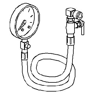
| • | J 44402 Fuel Tank Sending Unit Wrench |
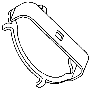
- Disconnect the negative battery cable.
- Relieve the fuel system pressure. Refer to Fuel Pressure Relief .
- Drain the fuel tank. Refer to Fuel Tank Draining .
- Remove the fuel tank. Refer to Fuel Tank Replacement .
- Remove the fuel sender assembly retaining ring using theJ 44402 Fuel Tank Sending Unit Wrench.
- Remove the fuel sender assembly and the seal. Discard the seal.
- Clean the fuel sender sealing surfaces.
Caution: Unless directed otherwise, the ignition and start switch must be in the OFF or LOCK position, and all electrical loads must be OFF before servicing any electrical component. Disconnect the negative battery cable to prevent an electrical spark should a tool or equipment come in contact with an exposed electrical terminal. Failure to follow these precautions may result in personal injury and/or damage to the vehicle or its components.
Notice: Do Not handle the fuel sender assembly by the fuel pipes. The amount of leverage generated by handling the fuel pipes could damage the joints.
Caution: Drain the fuel from the fuel sender assembly into an approved container in order to reduce the risk of fire and personal injury. Never store the fuel in an open container.
Installation Procedure
- Install the new seal on the fuel tank.
- Install the fuel sender assembly into the fuel tank.
- Install the fuel sender assembly retaining ring using theJ 44402 Fuel Tank Sending Unit Wrench.
- Install the fuel tank. Refer to Fuel Tank Replacement .
- Refill the fuel tank.
- Tighten the fuel filler cap.
- Connect the negative battery cable.
- Inspect for leaks.
Caution: In order to reduce the risk of fire and personal injury that may result from a fuel leak, always replace the fuel sender gasket when reinstalling the fuel sender assembly.
Important: The fuel strainer must be in a horizontal position when the fuel sender is installed in the tank. When installing the fuel sender assembly, assure that the fuel strainer does not block full travel of the float arm.
Notice: Use the correct fastener in the correct location. Replacement fasteners must be the correct part number for that application. Fasteners requiring replacement or fasteners requiring the use of thread locking compound or sealant are identified in the service procedure. Do not use paints, lubricants, or corrosion inhibitors on fasteners or fastener joint surfaces unless specified. These coatings affect fastener torque and joint clamping force and may damage the fastener. Use the correct tightening sequence and specifications when installing fasteners in order to avoid damage to parts and systems.
| 8.1. | Turn ON the ignition for 2 seconds. |
| 8.2. | Turn OFF the ignition for 10 seconds. |
| 8.3. | Turn ON the ignition. |
| 8.4. | Inspect for fuel leaks. |
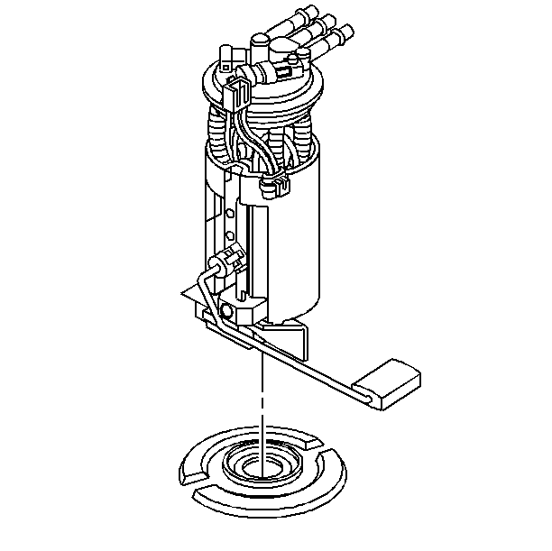
Fuel Sender Assembly Replacement Pick-Up
Removal Procedure
- Disconnect the negative battery cable.
- Relieve the fuel system pressure. Refer to Fuel Pressure Relief .
- Remove the pickup box. Refer to Pickup Box Replacement in Body Rear End.
- Disconnect the fuel sender electrical connectors.
- Disconnect the fuel sender fuel and evaporative emission (EVAP) pipes.
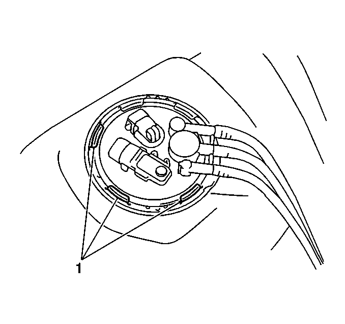
- While holding the modular fuel sender assembly down, remove the snap ring from designated slots (1) located on the retainer.
Caution: In order to reduce the risk of fire and personal injury that may result from a fuel leak, always replace the fuel sender gasket when reinstalling the fuel sender assembly.
Caution: Unless directed otherwise, the ignition and start switch must be in the OFF or LOCK position, and all electrical loads must be OFF before servicing any electrical component. Disconnect the negative battery cable to prevent an electrical spark should a tool or equipment come in contact with an exposed electrical terminal. Failure to follow these precautions may result in personal injury and/or damage to the vehicle or its components.
Important:
• The modular fuel sender assembly may spring up from the fuel tank. • When removing the modular fuel sender assembly from the fuel tank,
be aware that the reservoir bucket is full of fuel. The fuel sender assembly
must be tipped slightly during removal to avoid damage to the
float. Discard fuel sender O-ring and replace with a new one. • Carefully discard the reservoir fuel into an approved container.
Installation Procedure
- Install a new O-ring on the modular fuel sender to the tank.
- Align the tab on front of the modular sender with slot on front of the retainer snap ring.
- Slowly apply pressure to top of the spring loaded sender until the sender aligns flush with retainer on the tank.
- Insert snap ring into designated slots (1).
- Connect the fuel sender fuel and EVAP pipes.
- Connect the fuel sender electrical connectors.
- Connect the negative battery cable.
- Inspect for fuel leaks through the following steps:
- Install the pickup box. Refer to Pickup Box Replacement in Body Rear End.
Important: Ensure that the snap ring is fully seated within the tab slots.
| 8.1. | Turn ON the ignition for 2 seconds. |
| 8.2. | Turn OFF the ignition for 10 seconds. |
| 8.3. | Turn ON the ignition. |
| 8.4. | Inspect for fuel leaks. |
