Brake Rotor Lateral Runout Check Front
Tools Required
J 8001 Dial Indicator
Set
- Remove the tire and the wheel. Refer to
Tire and Wheel Removal and Installation
in Tires and Wheels
- Tighten the wheel nuts so that the rotor is tight against the
hub (JC1 system only).
- Adjust the wheel bearings in order to eliminate excessive free
play (RWD pickups only). Refer to
Wheel Bearing Adjustment
in Front Suspension.
- Clean the rotor surface.

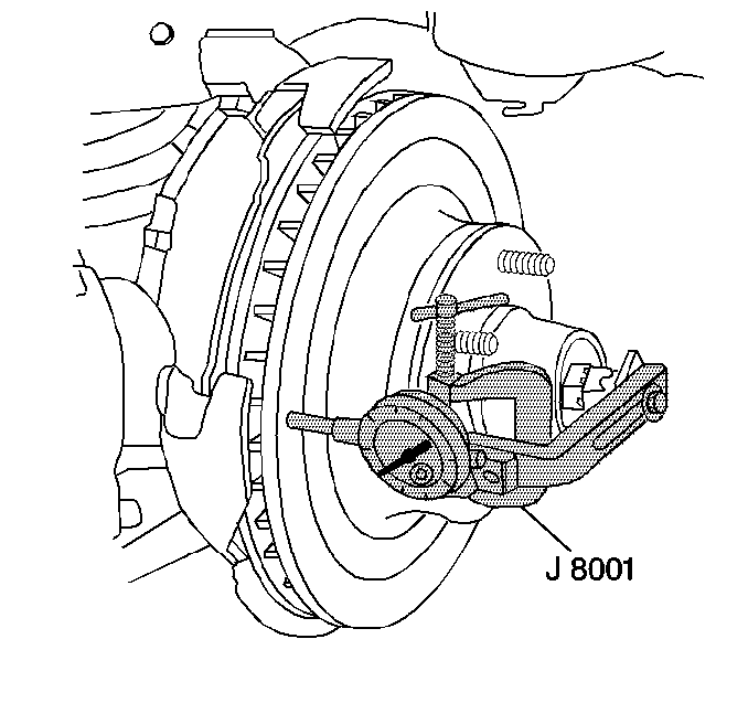
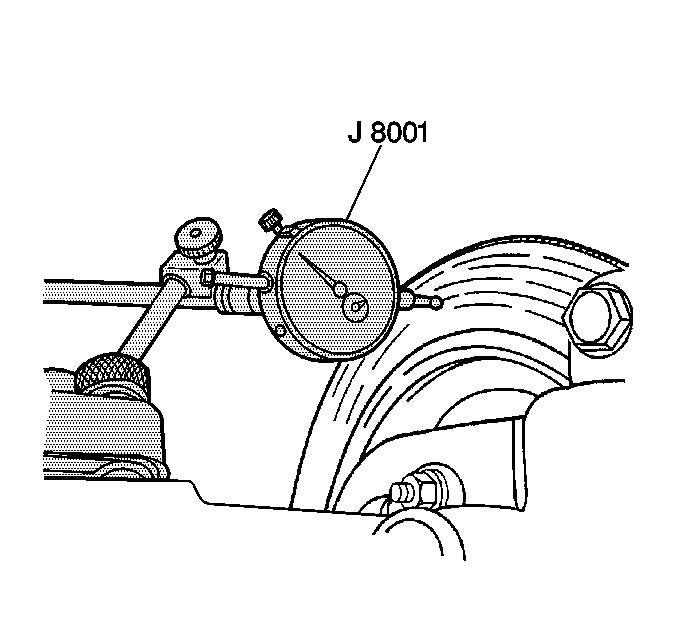
- Install the J 8001
so that the dial indicator button contacts
the rotor surface about 25 mm (1.0 in) from the outer edge.
- Set the dial indicator to zero.
- Turn the rotor one complete revolution and observe the lateral
runout on the dial indicator. The total indicator runout (TIR) should not
exceed 0.08 mm (0.003 in).
- If lateral runout is not within specifications refinish or replace
the rotor (RWD pickups only).
- In some cases, excessive lateral runout can be rectified by indexing
the rotor. Move the rotor one or two wheel bolt positions from the original
position (JC1 system only).
- If the lateral runout still exceeds 0.08 mm (0.003 in),
check the hub for excessive lateral runout, or looseness (JC1 system only).
| 10.2. | Reposition the J 8001
so that the button contacts the surface of the hub. |
| 10.3. | Set the dial indicator to zero. |
| 10.4. | Rotate the hub one complete revolution. |
| 10.5. | Note the lateral runout. |
| 10.7. | If the hub lateral runout is within specifications, refinish or
replace the rotor. Refer to
Brake Rotor Refinishing
. |
Brake Rotor Lateral Runout Check Rear
Tools Required
J 8001 Dial Indicator Set
- Remove the tire and the wheel. Refer to
Tire and Wheel Removal and Installation
in Tires and Wheels.
- Tighten the wheel nuts so that the rotor is tight against the axle flange.
- Clean the rotor surface.

- Install the J 8001
so that
the dial indicator button contacts the rotor surface about 13 mm (0.5 in)
from the outer edge.
- Push in the rear axle while setting the dial indicator to zero.
- While maintaining the inward pressure, turn the rotor one complete revolution.
- Observe the lateral runout on the dial indicator. The total indicator
runout (TIR) should not exceed 0.10 mm (0.004 in).
- In some cases, excessive lateral runout can be rectified by indexing
the rotor. Move the rotor one or two wheel bolt positions from the original position.
- If the lateral runout still exceeds 0.10 mm (0.004 in),
check the rear axle shaft flange for excessive lateral runout, or looseness.
| 9.2. | Reposition the J 8001
so that the button contacts the surface of the axle shaft flange. |
| 9.3. | Push the axle shaft flange inward while turning the axle shaft flange
one full revolution. |
| 9.4. | Continue pushing in the axle shaft flange while setting the dial indicator
to zero. |
| 9.5. | While maintaining the inward pressure, rotate the axle shaft flange one
complete revolution. |
| 9.6. | Note the lateral runout. |
| 9.7. | If the axle shaft flange lateral runout exceeds 0.05 mm (0.002 in),
replace the rear axle shaft. Refer to
Rear Axle Shaft Replacement
in Rear Drive Axle. |
| 9.8. | If the axle shaft flange lateral runout is within specifications, refinish
or replace the rotor. Refer to
Brake Rotor Refinishing
. |


