Tools Required
J 21366 Converter Holding Strap
Removal Procedure
Notice: Whenever you remove the transmission for service, you must perform the automatic transmission oil cooler flushing procedure in order to remove the existing fluid which may be contaminated. This will prevent contamination of the new fluid. You must perform the flushing procedure after the installation of the overhauled or replacement transmission.
Perform a pressure test before removing the automatic transmission. This will help to aid in the diagnosis of the transmission.
- Disconnect the negative battery cable.
- Remove the air intake duct.
- Disconnect the electrical connector from the intake air temperature sensor.
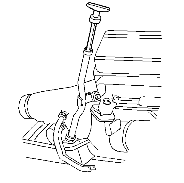
- Remove the transmission fluid level indicator.
- Raise the vehicle. Suitably support the vehicle. Refer to General Vehicle Lifting and Jacking in General Information.
- Remove the 3-way catalytic converter (3800 VIN K). Refer to Catalytic Converter Replacement .
- Remove the range selector lever cable from the transmission. Refer to Shift Cable Replacement .
- Remove the center support bearing from the torque arm (3800 VIN K). Refer to Propeller Shaft.
- Remove the propeller shaft. Refer to Propeller Shaft.
- Support the rear axle with a jack.
- Remove the rear axle torque arm. Refer to Torque Arm Replacement in Rear Suspension.
- Remove the starter motor. For the 3800 VIN K, refer to Starter Motor Replacement .
- Loosen the right side rear engine mount bracket bolt (3800 VIN K).
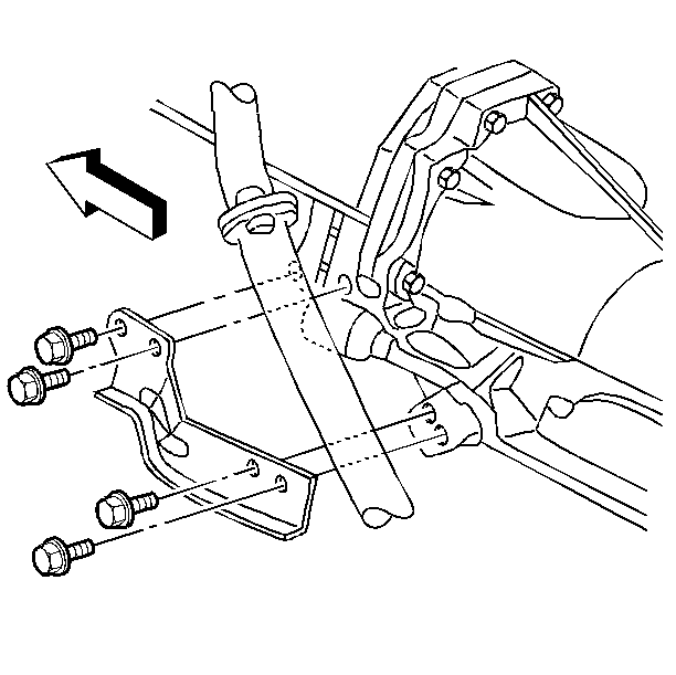
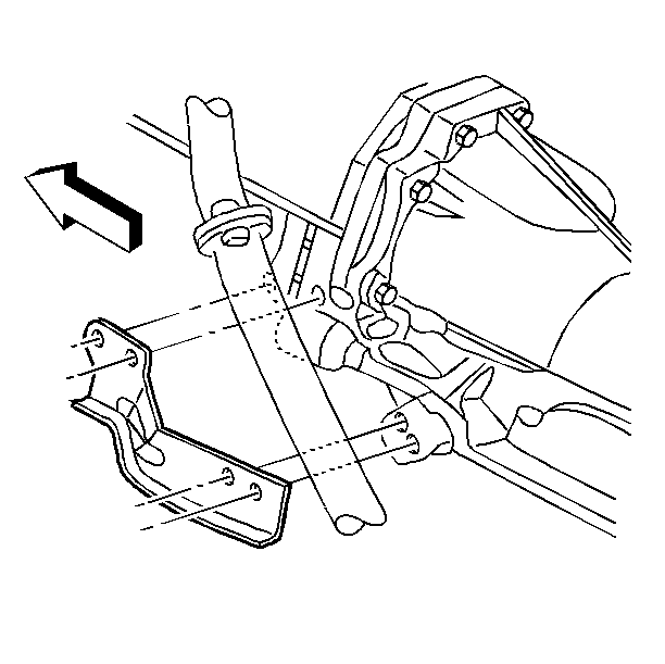
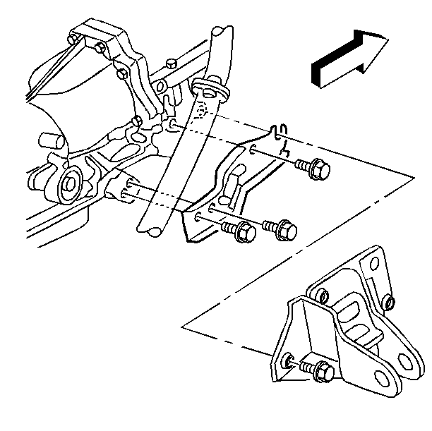
- Remove the bolts from the left transmission support brace.
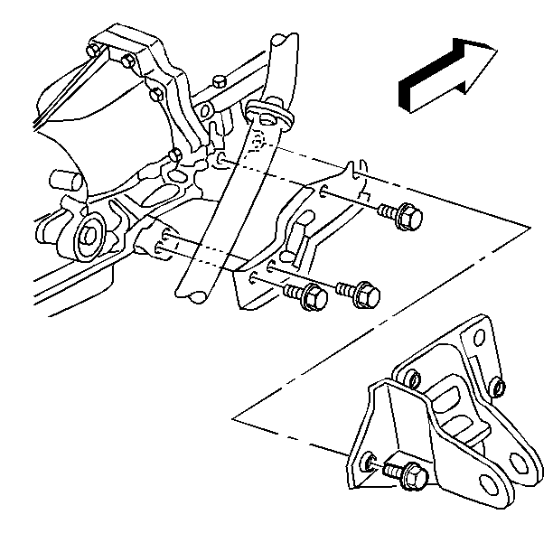
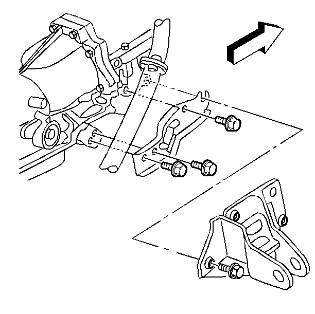
- Remove the bolts from the right transmission support brace.
- Remove the left transmission support brace from the vehicle.
- Remove the right transmission support brace from the vehicle.
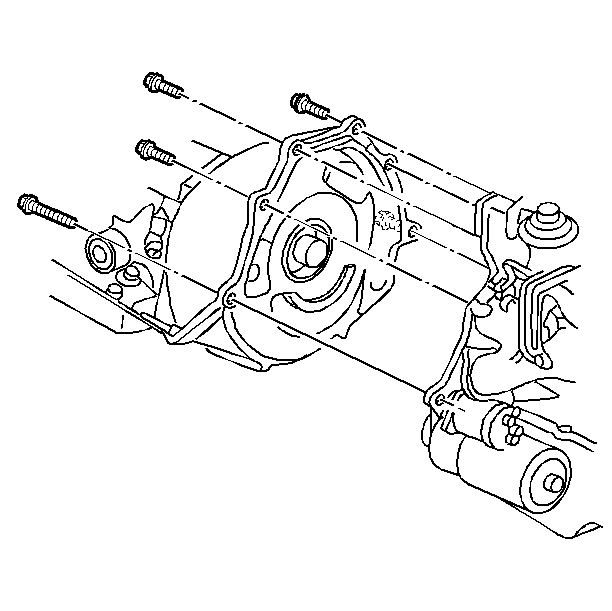
- Remove the transmission converter cover bolts and the cover.
- Remove the torque converter bolts attaching the flywheel to the torque converter. Refer to Flywheel Replacement.
- Remove the transmission oil cooler pipes.
- Disconnect the electrical connectors at the transmission.
- Support the transmission. Use a transmission jack.
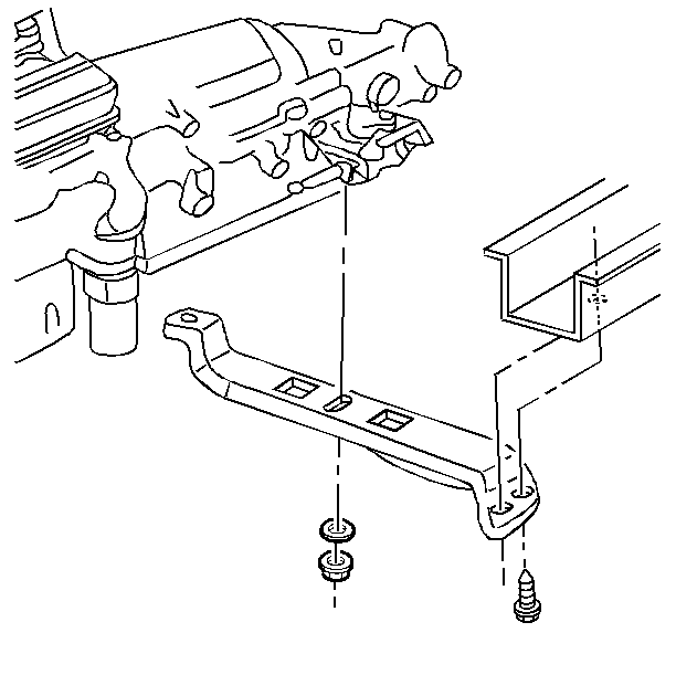
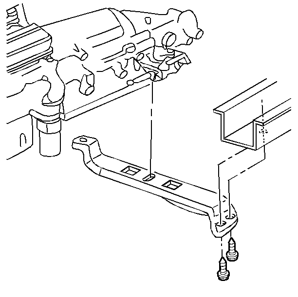
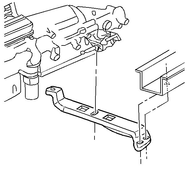
- Remove the washer and the nut from the support and the transmission.
- Remove the support bolts from the support and the rail.
- Remove the transmission support.
- Remove the transmission to engine bolts.
- Remove the transmission fluid fill tube. Refer to Filler Tube Replacement .
- Separate the transmission from the engine. Attach the J 21366 .
- Lower the transmission from the vehicle.
Caution: Unless directed otherwise, the ignition and start switch must be in the OFF or LOCK position, and all electrical loads must be OFF before servicing any electrical component. Disconnect the negative battery cable to prevent an electrical spark should a tool or equipment come in contact with an exposed electrical terminal. Failure to follow these precautions may result in personal injury and/or damage to the vehicle or its components.
Installation Procedure
- Raise the transmission into the vehicle.
- Remove the J 21366 .
- Align the transmission to the engine.
- Install the transmission fluid fill tube. Refer to Filler Tube Replacement .
- Install the transmission to engine bolts.
- Install the transmission support.
- Install the support bolts to the support and the rail.
- Install the washer and the nut to the support and the transmission.
- Remove the transmission jack.
- Connect the electrical connectors to the transmission.
- Install the transmission oil cooler lines.
- Install the torque converter bolts attaching the torque converter to the flywheel. Refer to Flywheel Replacement.
- Install the torque converter cover and the cover bolts.
- Install the left transmission support brace.
- Install the right transmission support brace.
- Install the bolts to the left transmission support brace.
- Install the bolts to the right transmission support brace.
- Tighten the rear engine mount bracket bolt on the right side (3800 VIN K).
- Install the starter motor. For the 3800 VIN K, refer to Starter Motor Replacement .
- Install the rear axle torque arm. Refer to Torque Arm Replacement in Rear Suspension.
- Remove the support from the rear axle.
- Install the propeller shaft. Refer to Propeller Shaft.
- Install the center support bearing to the torque arm (3800 VIN K). Refer to Propeller Shaft.
- Install the automatic transmission range selector lever cable. Refer to Shift Cable Replacement .
- Install the 3-way catalytic converter (3800 VIN K). Refer to Catalytic Converter Replacement .
- Lower the vehicle.
- Install the transmission fluid level indicator.
- Install the electrical connector to the intake air temperature sensor.
- Install the air intake duct.
- Connect the negative battery cable.
- Clean the transmission oil cooler, oil cooler pipes, and the hoses. Refer to Transmission Cooler Flushing
- Adjust the automatic transmission shift control lever cable. Refer to Shift Cable Replacement .
- Check the transmission fluid level. Ensure that the fluid level is filled to the proper specifications.

Tighten
| • | Tighten the bolts to 47 N·m (35 lb ft). |
| • | Tighten the bolts to 95 N·m (70 lb ft). |
Notice: Use the correct fastener in the correct location. Replacement fasteners must be the correct part number for that application. Fasteners requiring replacement or fasteners requiring the use of thread locking compound or sealant are identified in the service procedure. Do not use paints, lubricants, or corrosion inhibitors on fasteners or fastener joint surfaces unless specified. These coatings affect fastener torque and joint clamping force and may damage the fastener. Use the correct tightening sequence and specifications when installing fasteners in order to avoid damage to parts and systems.


Tighten
| • | Tighten the bolts to 28 N·m (21 lb ft). |
| • | Tighten the bolts to 50 N·m (37 lb ft). |

Tighten
Tighten the bolts to 50 N·m (37 lb ft).

Tighten
Tighten the bolts to 50 N·m (37 lb ft).

Tighten
Tighten the negative battery cable to 15 N·m
(11 lb ft).
.
Notice: Whenever you remove the transmission for service, you must perform the automatic transmission oil cooler flushing procedure in order to remove the existing fluid which may be contaminated. This will prevent contamination of the new fluid. You must perform the flushing procedure after the installation of the overhauled or replacement transmission.
