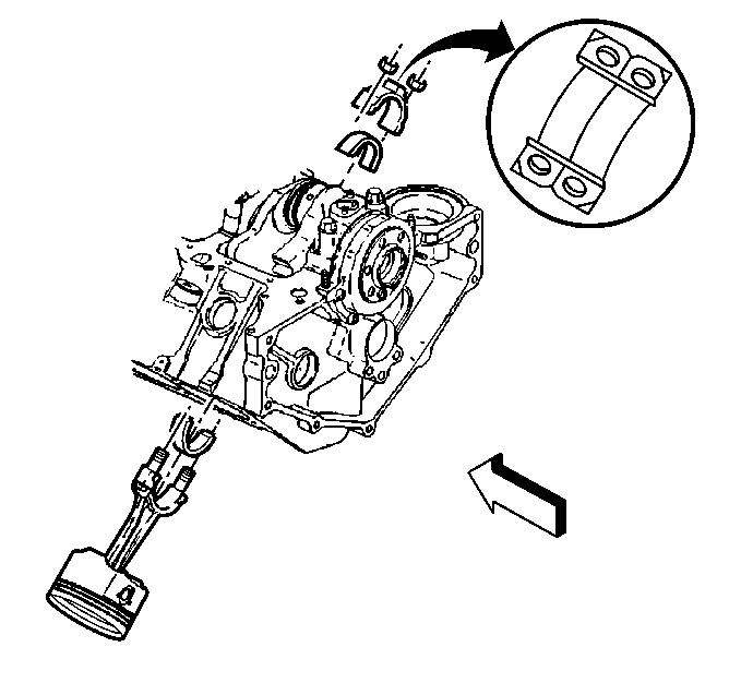
Tool Required
J 36660-A Torque Angle Meter
Removal Procedure
- Remove the oil pan. Refer to Oil Pan Replacement .
- Remove the oil pump. Refer to Oil Pump Replacement .
- Remove the connecting rod nuts.
- Remove the connecting rod cap and the bearings.
- Keep the bearings with the original connecting rod and the connecting rod cap for reassembly.
- Wipe the oil from the bearings and the crankpins.
- Inspect the bearings for excessive wear or damage.
- Measure the crankpin for out of round and taper with a micrometer.
- If not within specifications, replace or recondition the crankshaft.
- If installing new bearings, determine new bearing size from the maximum crankpin diameter.
- Measure the bearing clearance, using plastigage.
- Place a piece of plastigage the full width of the bearing onto the crankpin.
- The plastigage should be positioned in the middle of the bearing. The bearing is thickest in the center and the bearing clearance must be measured at this location.
- Install the connecting rod cap with the bearing onto the connecting rod.
- Install the connecting rod nuts.
- Remove the connecting rod nuts and the connecting rod cap.
- Measure the plastigage at the widest part, using the scale provided with the plastigage.
- If the clearance is greater than specified, select an undersize bearing and re-measure the clearance.
- If the clearance cannot be brought to specifications, regrind the crankpin. If the crankpin is already at maximum undersize, replace the crankshaft.
- Remove the plastigage.
Important: Connecting rod bearings are the precision insert type and do not use
shims for adjustments. Do not file connecting rods or rod caps. If the clearances
are found to be excessive, a new bearing will be required. Service bearings
are available in the following sizes:
• Standard size and 0.025 mm (0.001 in) and 0.05 mm
(0.002 in) undersize for use with new and used standard size crankshafts. • 0.025 mm (0.010 in) and 0.5 mm (0.020 in)
undersize for use with reconditioned crankshafts.
Important: Place numbers on the connecting rods and the connection rod caps. The connecting rod caps must be assembled with the original connecting rods.

Notice: Use the correct fastener in the correct location. Replacement fasteners must be the correct part number for that application. Fasteners requiring replacement or fasteners requiring the use of thread locking compound or sealant are identified in the service procedure. Do not use paints, lubricants, or corrosion inhibitors on fasteners or fastener joint surfaces unless specified. These coatings affect fastener torque and joint clamping force and may damage the fastener. Use the correct tightening sequence and specifications when installing fasteners in order to avoid damage to parts and systems.
Tighten
| • | On the first pass, tighten the nuts evenly to 27 N·m (20 lb ft). |
| • | On the final pass, use the J 36660-A in order to tighten the nuts an additional 55 degrees. |
Notice: Do not turn the crankshaft with the gauging plastic installed or the accuracy of the measurement will be affected.
The plastigage will be found adhering to either the connecting rod cap or crankshaft journal. Leave the plastigage in place to measure the component.
Installation Procedure
- Coat the inside surface of the bearings with the engine oil.
- Install the connecting rod cap and the bearings.
- Install the connecting rod nuts.
- Measure the connecting rod side clearance as follows:
- Install the oil pump. Refer to Oil Pump Replacement .
- Install the oil pan. Refer to Oil Pan Replacement .

Tighten
| • | On the first pass, tighten the nuts evenly to 27 N·m (20 lb ft). |
| • | On the final pass, use the J 36660-A in order to tighten the nuts an additional 55 degrees. |
| 4.1. | When all the connecting rod bearings have been installed, tap each connecting rod lightly parallel to the crankpin to make sure they have clearance. |
| 4.2. | Measure the side clearance between the connecting rod caps using a feeler gauge or dial indicator. |
| 4.3. | The rod side clearance should be 0.16 to 0.35 mm (0.006 to 0.014 in). |
