Battery Electrical Drain/Parasitic Load Test Alternate
- Disconnect the battery negative cable. Refer to
Caution: Unless directed otherwise, the ignition and start switch must be in the OFF or LOCK position, and all electrical loads must be OFF before servicing any electrical component. Disconnect the negative battery cable to prevent an electrical spark should a tool or equipment come in contact with an exposed electrical terminal. Failure to follow these precautions may result in personal injury and/or damage to the vehicle or its components.
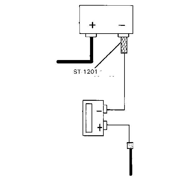
in General Information. - Install a battery side terminal adapter, AC Delco P/N ST-120 or GM P/M 12303040 or equivalent, in the negative battery terminal of the battery.
- Install the other battery side terminal adapter or a 3/8-inch nut with standard threads (16 NC) on the battery negative cable to assure a good electrical contact with the metal face on the cable for testing (add a washer behind the nut if the nut does not contact firmly). Yellow or black finish nuts are generally non-conductive and should not be used.
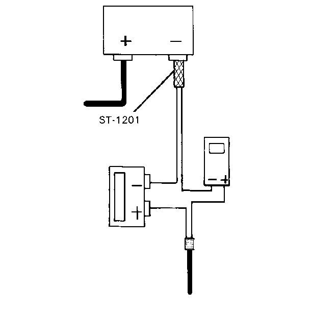
- With all lights, accessories, and the ignition switch off, connect a high capacity ammeter (at least 10 amps) from the battery negative cable to the side terminal adapter. This high capacity ammeter is connected to verify whether or not a high current draw is occurring at a constant rate. It is this type of high current draw which will blow the fuse in lower capacity ammeters.
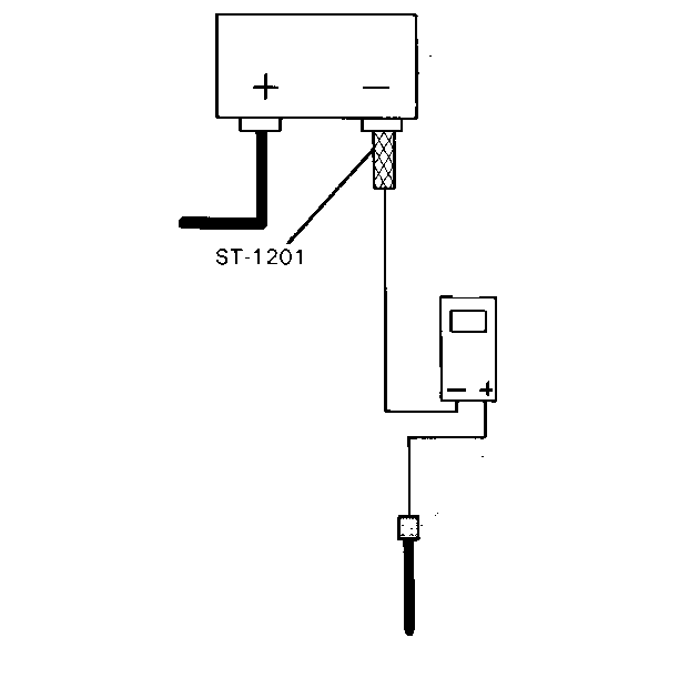
- With the high capacity ammeter or the battery cable section still connected, connect the digital multimeter, set on 300 mA dc range, in parallel with high reading ammeter.
- Disconnect the high capacity ammeter and take reading with the digital multimeter. If the current draw is above the specifications listed in the component parasitic load chart, remove the system fuses and the mini-breakers one at a time until the current draw returns to a valve less than or equal to the specifications listed. This should be done while monitoring the ammeter so that a disruption of drain will be evident. Set the ammeter on maximum scale when pulling fuses to avoid damage.
- When the cause of excessive draw has been located and repaired, repeat step 6 to verify the repair. Reconnect the battery negative cable to the battery negative terminal.
- Before performing a follow-up test drive, allow the HVAC to calibrate itself due to disconnecting the battery.


Important: If a high capacity ammeter is not available, install a section of heavy wire (preferably battery cable section) between the existing negative battery cable and the side terminal adapter. Allow time for an initial draw to occur or check for reduced current with an inductive ammeter (current clamp).

Tighten
Tighten the battery negative cable to 17 N·m (13 lb ft).
Notice: Use the correct fastener in the correct location. Replacement fasteners must be the correct part number for that application. Fasteners requiring replacement or fasteners requiring the use of thread locking compound or sealant are identified in the service procedure. Do not use paints, lubricants, or corrosion inhibitors on fasteners or fastener joint surfaces unless specified. These coatings affect fastener torque and joint clamping force and may damage the fastener. Use the correct tightening sequence and specifications when installing fasteners in order to avoid damage to parts and systems.
Battery Electrical Drain/Parasitic Load Test Parasitic Load Table
Application | Approximate Parasitic Draw (mA) | |
|---|---|---|
Keyless Entry | 2 | |
Voltage Regulator in Generator | 1 | |
HVAC Control Head-C68 (Before 2.5 hour timeout) | 13-15 | |
HVAC Control Head-C68 (After 2.5 hour timeout) | 5 | |
ELC Height Sensor (Before 6 minute timeout) | 400 | |
ELC Height Sensor (After 6 minute timeout) | 1 | |
PCM | 5-10 | |
Radio Control Head | 5 | |
PASS-Key II® (Theft Deterrent) Module | 5 | |
Battery Electrical Drain/Parasitic Load Test w/Tool
Parasitic Load Test
Tool Required
J 38758 Parasitic Draw Test Switch
If the battery discharges while the vehicle sits for a few hours or days, the vehicle should be diagnosed for parasitic loads. Simple connection of an ammeter in series with the battery may not find the cause as the condition may not show up when power is restored unless that particular component is repeatedly cycled. Parasitic loads can be diagnosed using either of the procedures below, but use of the special tool as described in the first procedure is recommended.
- Turn the test switch knob to the OFF position.
- Remove the battery negative cable. Refer to
Caution: Unless directed otherwise, the ignition and start switch must be in the OFF or LOCK position, and all electrical loads must be OFF before servicing any electrical component. Disconnect the negative battery cable to prevent an electrical spark should a tool or equipment come in contact with an exposed electrical terminal. Failure to follow these precautions may result in personal injury and/or damage to the vehicle or its components.
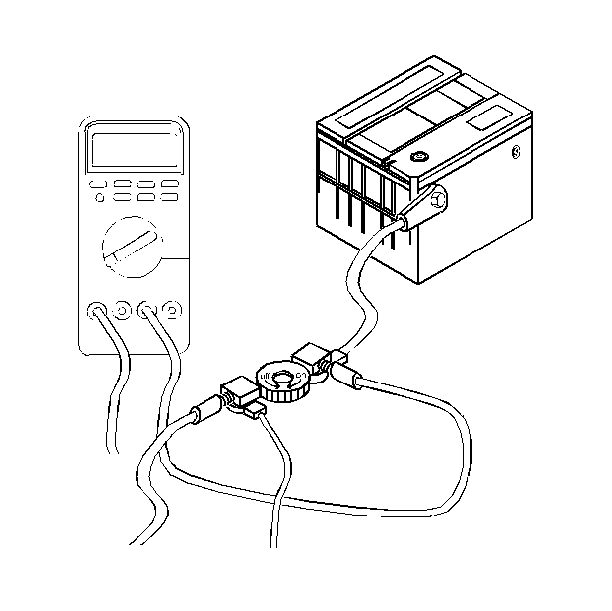
in General Information. - Install the parasitic draw test switch male (cable) end to the negative battery terminal.
- Install the battery negative cable the female end of the test switch tool.
- Turn the test switch tool knob to the ON position.
- Road test the vehicle while activating all accessories (radio, A/C, etc.).
- Turn the ignition switch to the Locked position and remove the ignition key.
- Disconnect the underhood lamp.
- Set the ammeter to the 10-amp scale and connect to the terminals on the test switch tool with alligator clips. Use of the 10-amp scale may prevent damage to the meter.
- Turn the test switch tool knob to the OFF position in order to allow current flow through the ammeter.
- Check the current reading. Allow time for the reading to stabilize. The Electronic Level Control (ELC) will remain active for 6 minutes. If the current reading is at or below two amps, turn the test tool knob to the ON position (in order to maintain continuity in the electrical system) and switch to a lower scale for a more accurate reading, or install a more accurate meter, if necessary. Turn the test tool knob to OFF. If the current reading is above 25 milli-amps, refer to Battery Electrical Drain/Parasitic Load Test for specific current loads and microprocessor time-outs for modules in awake and asleep states. A total reading below 20 milli-amps is normal and a reading below 25 milli-amps is acceptable. A zero reading indicates a problem with the meter, the scale being used, or the connection.
- If the current draw is above the specifications listed in the component parasitic load chart, remove the system maxi-fuses and circuit breakers one at a time until the current draw returns to a value less than or equal to the specifications listed. Refer to Battery Electrical Drain/Parasitic Load Test . This should be done while monitoring the ammeter so that a disruption of the drain will be evident. Perform steps 10 and 11 each time a fuse is removed. The total readings in the hundreds of milli-amps may suggest grounded wires, sticking relays, or small lamps remaining lit.
- When the cause of excessive current draw has been located and repaired, repeat steps 10 and 11 to verify the repair. Then turn the test tool to OFF, remove the tool, and reconnect the battery negative cable to the battery negative terminal.

NOTICE: The parasitic draw test should never be turned to the OFF position with the engine running or damage could occur to the vehicle's electrical system.
Important: Always turn the test switch tool knob to the ON position before removing each fuse to maintain continuity in the electrical system and to avoid damaging the ammeter due to accidental overloading (i.e., opening door). Do not turn the switch to OFF while the engine is running.
Before performing a follow-up test drive, allow HVAC to calibrate itself due to disconnecting the battery.
Tighten
Tighten the negative battery cable to 17 N·m (13 lb ft).
Notice: Use the correct fastener in the correct location. Replacement fasteners must be the correct part number for that application. Fasteners requiring replacement or fasteners requiring the use of thread locking compound or sealant are identified in the service procedure. Do not use paints, lubricants, or corrosion inhibitors on fasteners or fastener joint surfaces unless specified. These coatings affect fastener torque and joint clamping force and may damage the fastener. Use the correct tightening sequence and specifications when installing fasteners in order to avoid damage to parts and systems.
