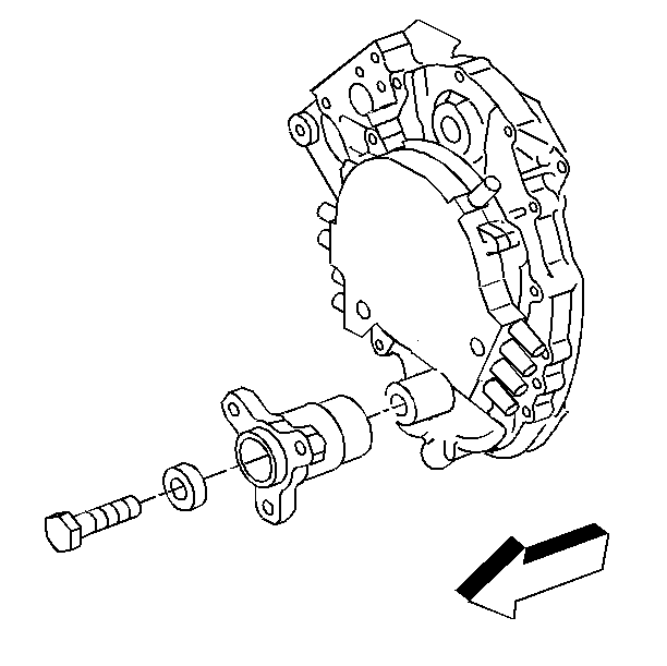
Removal Procedure
Tools Required
J 39046 Crankshaft Hub Remover/Installer
- Raise the vehicle, if equipped with mechanical fan.
- Suitably support the vehicle. Refer to General Vehicle Lifting and Jacking in General Information.
- Remove the accessory drive belt. Refer to Drive Belt Replacement
- Remove the crankshaft pully bolts and the pully, if equipped with a mechanical fan.
- Remove the crankshaft balancer bolts.
- Remove the crankshaft balancer.
- Match mark the crankshaft hub to the engine front cover.
- Do not crank the engine over after match marking the crankshaft hub and the engine front cover. Rotating the crankshaft will cause misalignment of the crankshaft balancer to the crankshaft, possibly resulting in engine imbalance.
- Remove the crankshaft hub bolt and the crankshaft washer.
- Remove the crankshaft hub using the J 39046

Installation Procedure
Tools Required
J 39046 Crankshaft Hub Remover/Installer
- Install the crankshaft hub using the J 39046 .
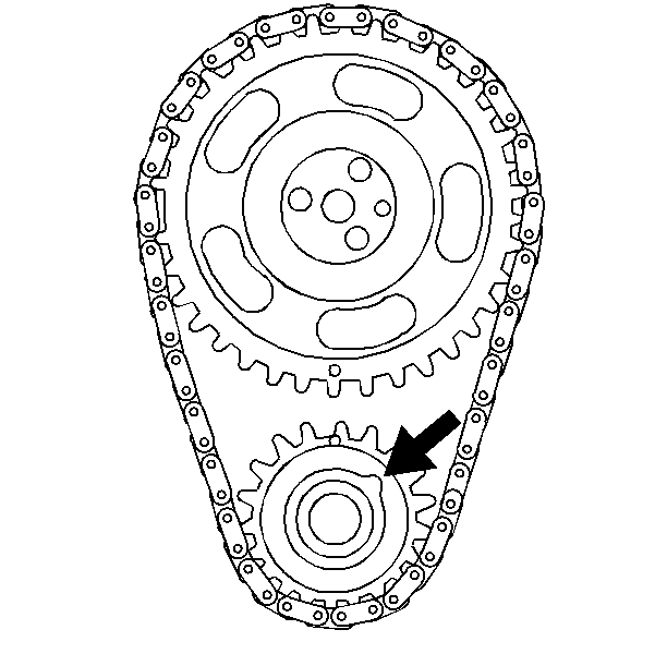
- If the engine should accidentally be cranked over after match marking the hub and the engine front cover, install the crankshaft hub as follows:
- Install the crankshaft hub balancer.
- Install the crankshaft hub bolt.
- Install the crankshaft balancer bolts.
- Install the crankshaft pulley and the bolts if removed.
- Install the accessory drive belt. Refer to Drive Belt Replacement .
- Lower the vehicle.


| 2.1. | Set the number 1 piston to the top dead center. |
| 2.2. | View the crankshaft from the front. The crankshaft keyway must be in the position shown. |
| 2.3. | Install the crankshaft hub with the cast arrow on the hub in the 12 o'clock position. |
Important: If balancer is replaced, install new balance weights of the same size on the new balancer in the same hole locations used on the old balancer.
Tighten
Tighten the crankshaft balancer hub bolt to 100 N·m (74 lb ft).
Notice: Use the correct fastener in the correct location. Replacement fasteners must be the correct part number for that application. Fasteners requiring replacement or fasteners requiring the use of thread locking compound or sealant are identified in the service procedure. Do not use paints, lubricants, or corrosion inhibitors on fasteners or fastener joint surfaces unless specified. These coatings affect fastener torque and joint clamping force and may damage the fastener. Use the correct tightening sequence and specifications when installing fasteners in order to avoid damage to parts and systems.
Tighten
Tighten the crankshaft balancer bolts to 85 N·m (63 lb ft).
Tighten
| • | Tighten crankshaft pulley bolts in a clockwise pattern to 10 N·m (89 lb ft). |
| • | Tighten again in a clockwise pattern to 25 N·m (18 lb ft). |
