Tools Required
Caution: Do not operate the detector in a combustible atmosphere since its sensor operates at high temperatures or personal injury and/or damage to the equipment may result.
J 39400-A Halogen Leak Detector.
Removal Procedure
- Disconnect the negative battery cable. Refer to Battery Negative Cable Disconnection and Connection.
- Recover the refrigerant from the system. Refer to Refrigerant Recovery and Recharging.
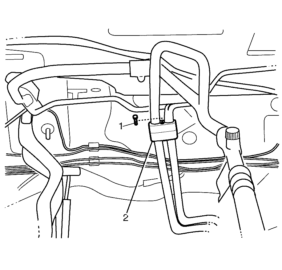
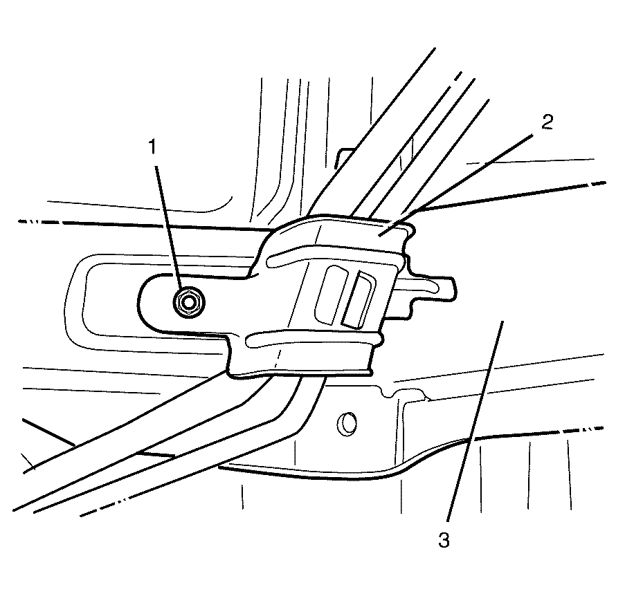
- Remove the auxiliary A/C evaporator and suction tube fastener (1) and disconnect the engine bay HVAC tubing assembly (2).
- Remove and discard the "O" Rings.
- Raise the vehicle. Refer to Lifting and Jacking the Vehicle.
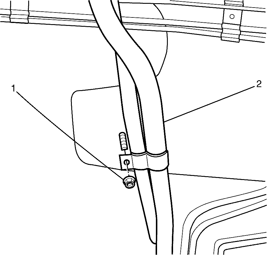
- Remove the auxiliary HVAC preliminary tubing assembly to bulkhead fastener (1) supporting the auxiliary HVAC preliminary tubing assembly (2).
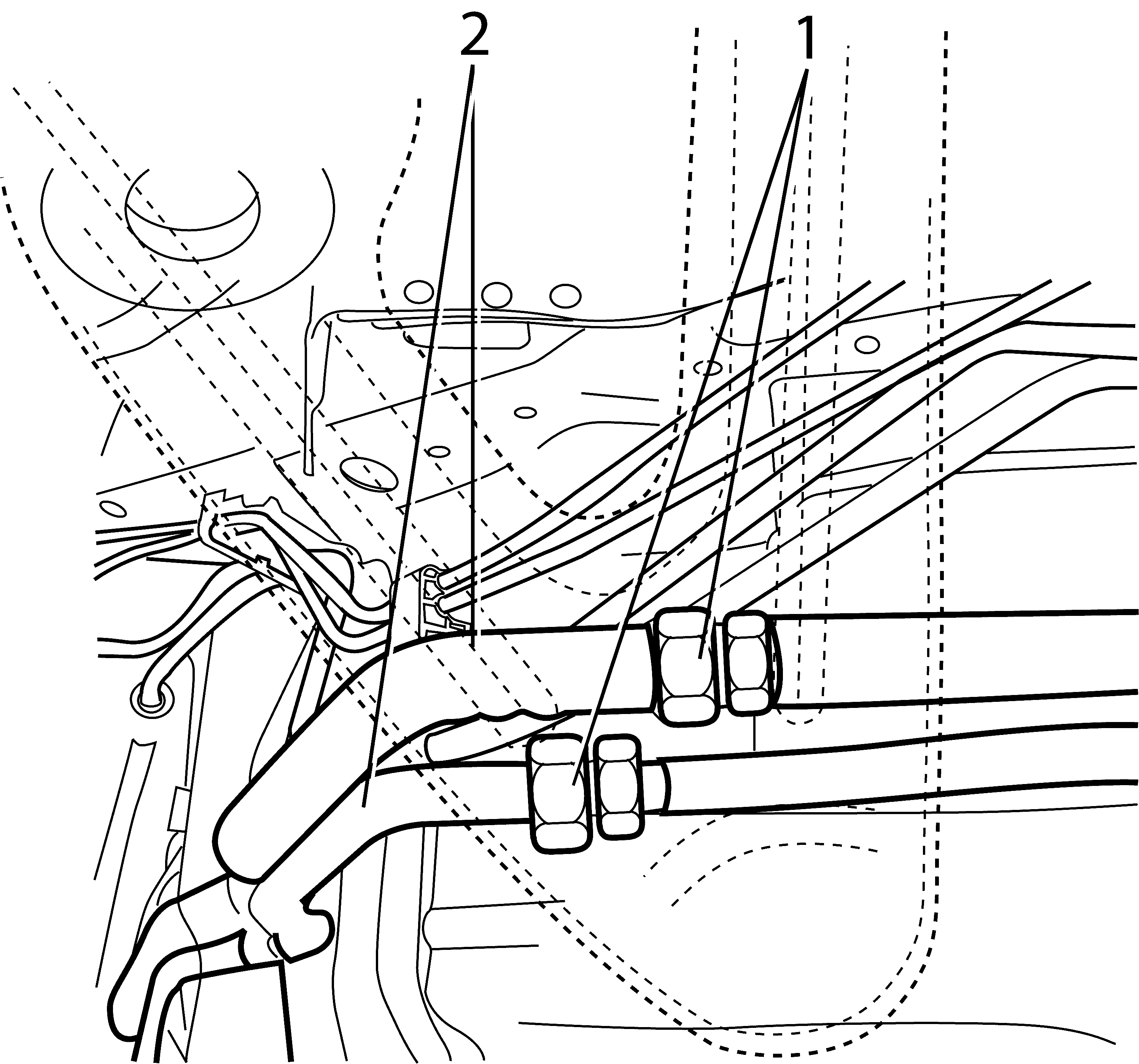
- Disconnect the auxiliary HVAC preliminary tubing connectors (1), and remove the auxiliary HVAC preliminary tubing assembly (2) from the vehicle.
- Remove and discard the "O" Rings.
- Remove the auxiliary HVAC preliminary tubing assembly to floorpan fastener (1) supporting the auxiliary HVAC preliminary tubing assembly (2).
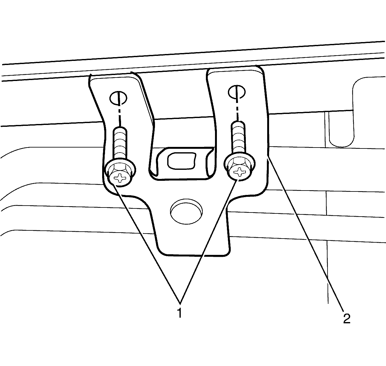
- Remove the auxiliary HVAC secondary tubing assembly support fasteners (1), from the auxiliary HVAC secondary tubing assembly support (2).
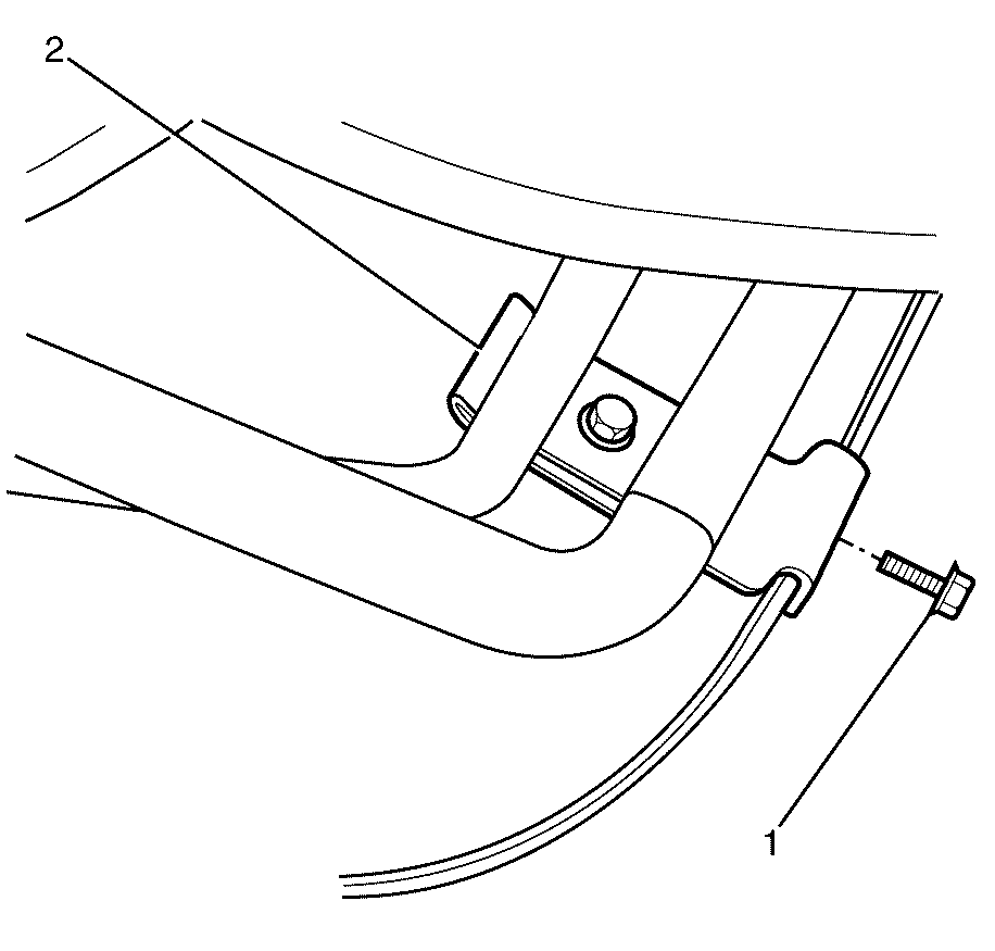
- Remove the secondary HVAC tubing support bracket fastener (1), and disengage the bracket locator tang (2) from the vehicle body (3).
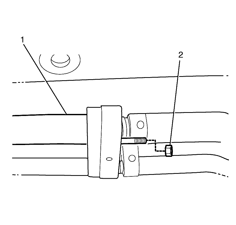
- Remove the auxiliary HVAC tubing fastener (2), and remove the auxiliary HVAC secondary tubing assembly (1) from the vehicle.
- Remove and discard the "O" Rings.
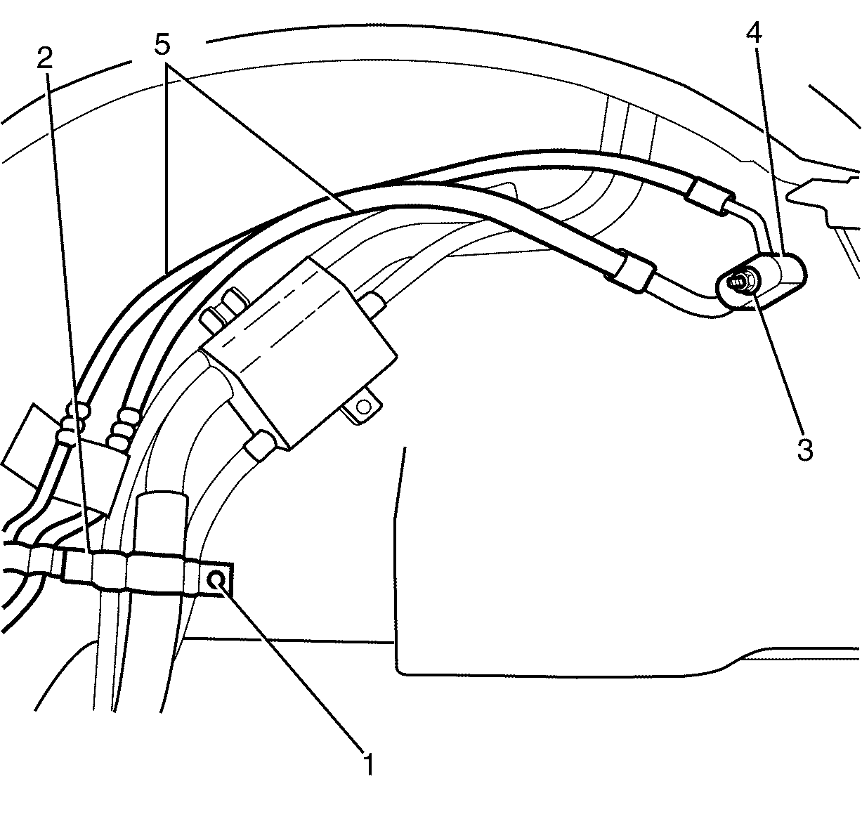
- Remove the third auxiliary HVAC tubing assembly support fastener (1) from the third auxiliary HVAC tubing assembly support (2).
- Remove the rear wheelhouse liner. Refer to Rear Wheelhouse Panel Liner Modification.
- Remove the third auxiliary HVAC tubing assembly to wheelhouse support fastener (1) and remove the third auxiliary HVAC tubing assembly to wheelhouse support (2).
- Remove the third auxiliary HVAC tubing assembly to auxiliary HVAC module fastener (3).
- Remove the third auxiliary HVAC tubing assembly (5) from the vehicle, disconnecting it from the auxiliary HVAC module connections (4).
- Remove and discard the "O" Rings.
Caution: Refer to Battery Disconnect Caution in the Preface section.

Installation Procedure
- Install the third auxiliary HVAC tubing assembly (5) onto the vehicle, engaging the connections with the auxiliary HVAC module (4).
- Connect the third auxiliary HVAC tubing assembly (5) to the auxiliary HVAC module connections (4).
- Install the third auxiliary HVAC tubing assembly to auxiliary HVAC module fastener (3).
- Install the third auxiliary HVAC tubing assembly support (2) and the third auxiliary HVAC tubing assembly to wheelhouse support fastener (1).
- Install the third auxiliary HVAC tubing assembly support (2) and the third auxiliary HVAC tubing assembly support fastener (1) into the vehicle.
- Install the rear wheelhouse liner. Refer to Rear Wheelhouse Panel Liner Modification.
- Install the auxiliary HVAC secondary tubing assembly (1) onto the vehicle and install the auxiliary HVAC secondary tubing assembly to third auxiliary HVAC tubing assembly fastener (2).
- Engage the bracket locator tang (2) into the vehicle body (3) and install the secondary HVAC tubing support bracket fastener.
- Install the auxiliary HVAC secondary tubing assembly support (2) and auxiliary HVAC secondary tubing assembly support fasteners (1).
- Install the auxiliary HVAC preliminary tubing assembly to floorpan fastener (1) supporting the auxiliary HVAC preliminary tubing assembly (2).
- Install the auxiliary HVAC preliminary tubing assembly (2), onto the vehicle, and connect the auxiliary HVAC preliminary tubing connectors (1).
- Install the auxiliary HVAC preliminary tubing assembly to floorpan fastener (1) supporting the auxiliary HVAC preliminary tubing assembly (2).
- Lower the vehicle. Refer to Lifting and Jacking the Vehicle.
- Install the auxiliary HVAC preliminary tubing assembly (3) and connect to the engine bay HVAC tubing assembly (2).
- Install the auxiliary A/C and suction tube fastener (1).
- Recharge the refrigerant in the HVAC system. Refer to Refrigerant Recovery and Recharging.
- Connect the negative battery cable. Refer to Battery Negative Cable Disconnection and Connection.
- Check the system operation.

Important: If replacing the rear wheelhouse liner with a new part, modifications must be made to the liner. Refer to Rear Wheelhouse Panel Liner Modification
Important: New "O" rings must be used on all HVAC evaporator and suction tubes connections. Ensure all "O" rings are well lubricated with air conditioning oil prior to installation.
Notice: Refer to Fastener Notice in the Preface section.
Tighten
Tighten the third auxiliary HVAC tubing assembly
to auxiliary HVAC module fastener to 16 N·m (12 lb ft).
Tighten
Tighten the third auxiliary HVAC tubing assembly
to wheelhouse support fastener to 10 N·m (89 lb in).

Tighten
Tighten the third auxiliary HVAC tubing assembly
support fastener to 10 N·m (7.37 lb ft).
Important: If replacing the rear wheelhouse liner with a new part, modifications must be made to the liner. Refer to Rear Wheelhouse Panel Liner Modification

Important: New "O" rings must be used on all HVAC evaporator and suction tubes connections. Ensure all "O" rings are well lubricated with air conditioning oil prior to installation.
Tighten
Tighten the auxiliary HVAC secondary tubing assembly
to third auxiliary HVAC tubing assembly fastener to 16 N·m (12 lb ft).

Tighten
Tighten the secondary HVAC tubing support bracket
fastener to 16 N·m (12 lb ft).

Tighten
Tighten the auxiliary HVAC secondary tubing assembly
support fasteners to 10 N·m (89 lb in).

Tighten
Tighten the auxiliary HVAC preliminary tubing assembly
to floorpan fastener to 10 N·m (89 lb in).

Important: New "O" rings must be used on all HVAC evaporator and suction tubes connections. Ensure all "O" rings are well lubricated with air conditioning oil prior to installation.
Tighten
Tighten the auxiliary HVAC preliminary evaporator
tubing connectors to 135 N·m (100 lb ft).

Tighten
Tighten the auxiliary HVAC preliminary tubing assembly
to floorpan fastener to 10 N·m (89 lb in).

Important: New "O" rings must be used on all HVAC evaporator and suction tubes connections. Ensure all "O" rings are well lubricated with air conditioning oil prior to installation.
Tighten
Tighten the auxiliary A/C and suction tube fastener
to 16 N·m (12 lb ft).
