For 1990-2009 cars only
Removal Procedure
- Remove the oil feed pipes. Refer to Oil Feed Pipes Replacement .
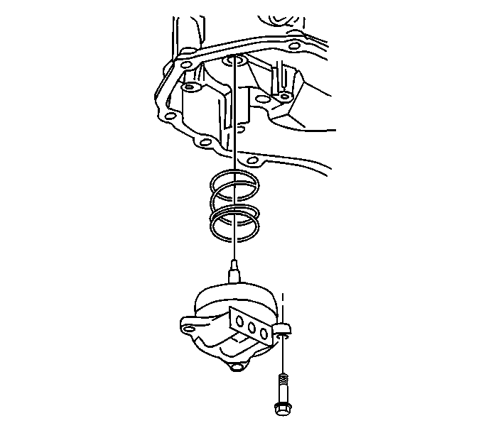
- Remove the 3 low and reverse band servo cover bolts, the servo, and the spring.

Disassembly Procedure
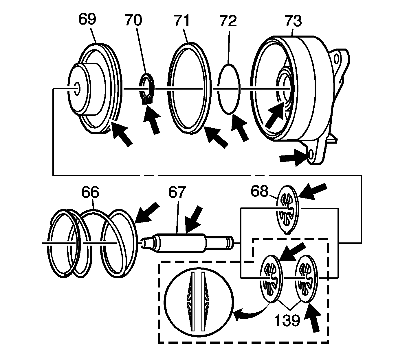
- Remove the piston pin assembly (67-70) from the servo cover (73).
- Remove the snap ring (70) from the servo pin (67).
- Remove the piston (69) and the servo cushion spring (68), or springs (139), from the servo pin (67).
- Remove the servo piston seals (71, 72) from the cover (73).
- Discard the servo piston seals (71 and 72).
- Inspect all the components for damage.
- Inspect the fluid feed holes for the proper opening.
- Inspect the bolt hole threads for debris or stripping.
- Inspect the seal grooves for damage.
- Clean and dry each component.

Assembly Procedure
- Assemble the servo cushion spring (68), or springs (139), and the servo piston (69) onto the servo pin (67).
- Install the snap ring onto the servo pin (67) in order to retain the servo cushion springs (68) and the servo piston (69).
- Assemble the new seals (71, 72) onto the servo piston (69) and the servo cover (73).
- Assemble the servo piston assembly (67-70) into the servo cover (73). Lubricate the piston seals with transmission fluid in order to aid in assembly.

Installation Procedure
- Install the low and the reverse band servo cover bolts.
- Install the oil feed pipe. Refer to Oil Feed Pipes Replacement .
- Reset the TAP values. Refer to Transmission Adaptive Functions .
Notice: Refer to Fastener Notice in the Preface section.

Tighten
Tighten the bolts to 12 N·m (106 lb in).
Important: It is recommended that transmission adaptive pressure (TAP) information be reset.
Resetting the TAP values using a scan tool will erase all learned values in all cells. As a result, the engine control module (ECM), powertrain control module (PCM) or transmission control module (TCM) will need to relearn TAP values. Transmission performance may be affected as new TAP values are learned.Removal Procedure
- Remove the oil feed pipes. Refer to Oil Feed Pipes Replacement.
- Remove the 3 low and reverse band servo cover bolts, the servo, and the spring.

Disassembly Procedure
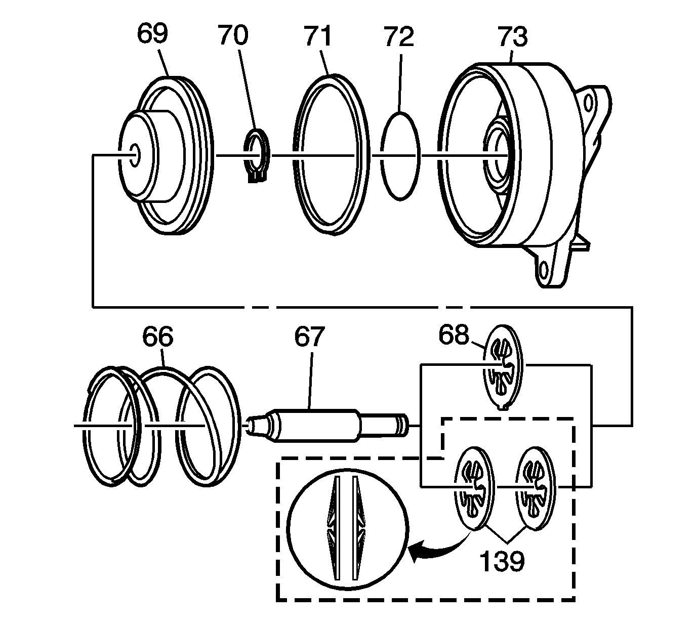
- Remove the piston pin assembly (67-70) from the servo cover (73).
- Remove the snap ring (70) from the servo pin (67).
- Remove the piston (69) and the servo cushion spring (68), or springs (139), from the servo pin (67).
- Remove the servo piston seals (71, 72) from the cover (73).
- Discard the servo piston seals (71 and 72).
- Inspect all the components for damage.
- Inspect the fluid feed holes for the proper opening.
- Inspect the bolt hole threads for debris or stripping.
- Inspect the seal grooves for damage.
- Clean and dry each component.

Assembly Procedure
- Assemble the servo cushion spring (68), or springs (139), and the servo piston (69) onto the servo pin (67).
- Install the snap ring onto the servo pin (67) in order to retain the servo cushion springs (68) and the servo piston (69).
- Assemble the new seals (71, 72) onto the servo piston (69) and the servo cover (73).
- Assemble the servo piston assembly (67-70) into the servo cover (73). Lubricate the piston seals with transmission fluid in order to aid in assembly.

Installation Procedure
- Install the low and the reverse band servo cover bolts and tighten to 12 N·m (106 lb in).
- Install the oil feed pipe. Refer to Oil Feed Pipes Replacement.
- Reset the TAP values. Refer to Transmission Adaptive Functions.
Caution: Refer to Fastener Caution in the Preface section.

Note: It is recommended that transmission adaptive pressure (TAP) information be reset.
Resetting the TAP values using a scan tool will erase all learned values in all cells. As a result, the engine control module (ECM), powertrain control module (PCM) or transmission control module (TCM) will need to relearn TAP values. Transmission performance may be affected as new TAP values are learned.