For 1990-2009 cars only
Tools Required
| • | J 26958 Output Shaft Aligning & Loading Tool |
| • | J 26958-10B Adaptor Plug |
| • | J 25025-7A Dial Indicator Post |
| • | J 28588 Gage |
| • | J 8001 Dial Indicator |
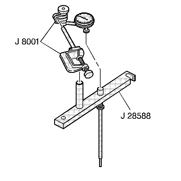
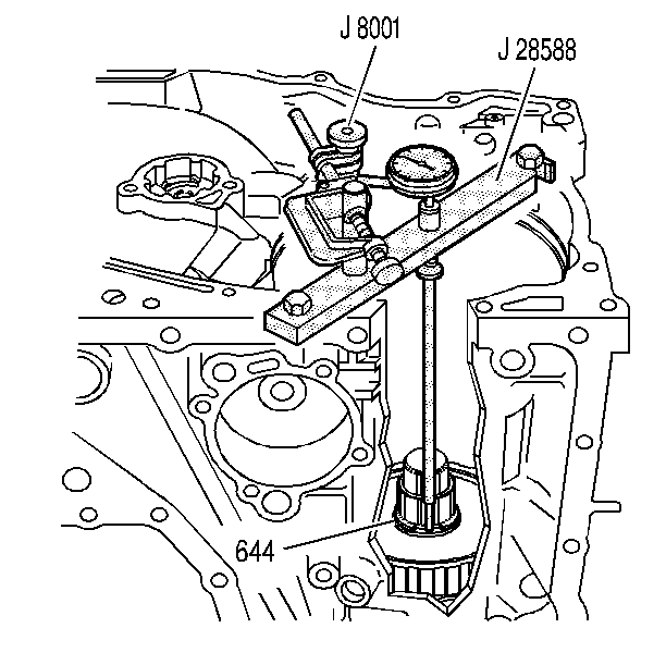
- Install J 28588 , J 8001 , and J 25025-7A .
- Position the gage extension between the open ends of the selective snap ring (644) on the reaction sun gear.
- Swing the feeler gage of J 28588 under the extension shoulder.
- Set the dial indicator so that the pointer is at zero.
- Position the selective snap ring (644) under the gage extension shoulder.
- Remove the feeler gage from under the extension shoulder.
- The dial indicator should read 0.33 to -0.33 mm (0.013 to -0.005 in)
- Record the reading.
- In order to select the correct snap ring, refer to the Reaction Sun Gear to Input Drum Selective Snap Ring table in End Play Specifications .
- Measure the new or used snap ring (644) with a micrometer.

Important: The J 26958 loading tool should still be in place from the input shaft end play check.


Tools Required
| • | J 26958 Output Shaft Aligning & Loading Tool |
| • | J 25025 Dial Indicator Post |
| • | J 28588 Gage |
| • | J 8001 Dial Indicator |
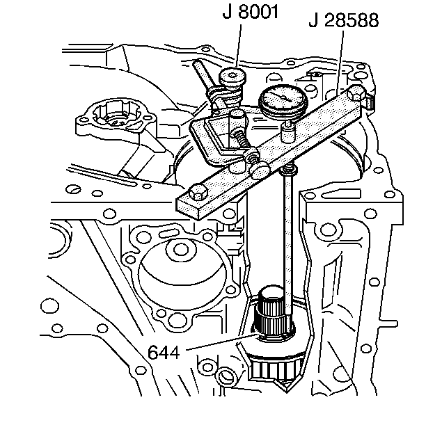
- Install J 28588 , J 8001 , and J 25025 .
- Position the gage extension between the open ends of the selective snap ring (644) on the reaction sun gear.
- Swing the feeler gage of J 28588 under the extension shoulder.
- Set the dial indicator so that the pointer is at zero.
- Position the selective snap ring (644) under the gage extension shoulder.
- Remove the feeler gage from under the extension shoulder.
- The dial indicator should read

Important: The J 26958 and J 26958-10B should still be in place from the Input Shaft End Play Check procedure.


