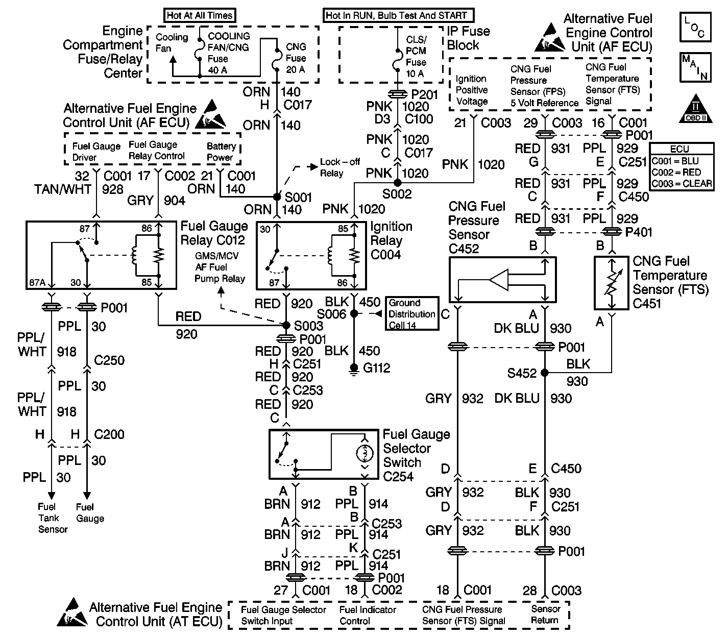
GM Service Manual Online
For 1990-2009 cars only

Object Number: 384594  Size: LF
Handling Electrostatic Discharge Sensitive Parts Notice
Engine Controls Components
CNG Fuel Controls (2 of 3)
OBDII Symbol Description Notice

Diagnostic Aids

Verify the following conditions:

    • Verify that the CNG fuel system is at least 1/4 full. Add fuel if needed.
    • Verify that the fuel pressure sensor (FPS) is connected.
    • Verify that the manual lock down screw in the HPL is open.

Important: The gauge will display the dormant fuel level for 10 seconds when the fuel gauge selector switch is depressed. It will then return to normal operation.

Step

Action

Value(s)

Yes

No

1

  1. Turn ON the ignition.
  2. Observe the fuel indicator lamp in the fuel gauge selector switch.
  3. The lamp should illuminate for approximately two seconds and then turn off.

Does the lamp cycle on and off?

--

Go to Step 7

Go to Step 2

2

Does the fuel indicator lamp remain illuminated?

--

Go to Step 3

Go to Step 5

3

  1. Start the vehicle.
  2. Close the CNG manual shut-off valve (MSV).

Does the vehicle switch fuel operation, stall or does the MIL illuminate?

--

Go to Step 14

Go to Step 4

4

  1. The vehicle should be operating in the gasoline mode.
  2. Open the MSV.

Is the action complete?

--

Go to Fuel System Unwanted Switch to Gasoline

--

5

  1. Turn OFF the ignition.
  2. Disconnect the fuel gauge selector switch harness connector C253.
  3. Connect a test light between CKT 914 (PPL) at terminal B and CKT 920 (RED) at terminal C.
  4. Turn ON the ignition.
  5. The test light should illuminate for approximately two seconds and then turn off.

Does the test light illuminate?

--

Go to Step 16

Go to Step 6

6

  1. Turn OFF the ignition.
  2. Connect the test light to ground.
  3. Turn ON the ignition.
  4. Probe CKT 920 (RED) at terminal C.

Does the test light illuminate?

--

Go to Step 10

Go to Step 13

7

  1. Turn OFF the ignition.
  2. Disconnect the fuel pressure sensor (FPS) connector C452.
  3. Important: If the CNG tank pressure is below 1200 psi, the vehicle will not attempt to start on CNG until the tank is refilled.

  4. Turn ON the ignition.
  5. Verify that the fuel mode indicator lamp is ON.
  6. Observe the fuel gauge and wait for the reading to stabilize.
  7. Depress the fuel gauge selector switch. The gauge reading should begin to move toward EMPTY indicating a CNG fuel level reading.

Does the fuel gauge reading change for ten seconds when the switch is depressed?

--

Go to Step 21

Go to Step 8

8

  1. Turn OFF the ignition.
  2. Disconnect the fuel gauge selector switch harness connector C253.
  3. Connect a DVOM set to read continuity between CKT 912 (BRN) terminal A and CKT 920 (RED) terminal C of the switch side of connector C253.
  4. Depress the fuel gauge selector switch several times while monitoring the DVOM.

Is there continuity when the switch is depressed?

--

Go to Step 9

Go to Step 15

9

  1. Connect the test light to ground.
  2. Turn ON the ignition.
  3. Probe CKT 920 (RED) at terminal C of the ECU side of connector C253.

Does the test light illuminate?

--

Go to Step 11

Go to Step 13

10

  1. Disconnect the ECU connector C002 (RED).
  2. Measure for continuity of the fuel mode indicator lamp circuit (914) between connector C002 and C253.

Is there continuity?

--

Go to Step 18

Go to Step 19

11

  1. Disconnect ECU connector C001 (BLU).
  2. Measure for continuity of CKT 912 (BRN) at terminal A of C253 to C001 (BLU) pin 27 using a DVOM.

Is there continuity?

--

Go to Step 12

Go to Step 19

12

Inspect for a poor fuel gauge selector switch circuit connection at ECU connector C001 (BLU).

Was a problem found?

--

Go to Step 19

Go to Fuel Gauge Relay Diagnosis

13

  1. Disconnect the ignition relay connector C004.
  2. Measure for continuity of CKT 920 between connectors C004 cavity 87 and C253 cavity C.

Is there continuity?

--

Go to Ignition Relay Diagnosis

Go to Step 19

14

  1. Disconnect ECU connector C002 (RED).
  2. Inspect the CKT 914 (PPL) at terminal B of connector C254 for a short to ground using a DVOM.

Was a problem found?

--

Go to Step 19

Go to Step 18

15

  1. Disconnect connector C254.
  2. Measure for continuity of the fuel gauge selector switch circuit (912) and the ignition power circuit (920) between connectors C254 and C253.

Was a problem found?

--

Go to Step 19

Go to Step 17

16

  1. Disconnect connector C254.
  2. Measure for continuity of the fuel mode indicator lamp circuit (914) and the ignition power circuit (920) between connectors C254 and C253.

Was a problem found?

--

Go to Step 19

Go to Step 17

17

Replace the fuel gauge selector switch. Refer to Fuel Gauge Selector Switch/Fuel Indicator Lamp Replacement Fuel Gauge Selector Sw./Fuel Ind. Lamp Replacement .

Is the action complete?

--

Go to Step 21

--

18

Inspect for a faulty, loose or corroded terminal connection at the ECU connectors.

Was a problem found?

--

Go to Step 19

Go to Step 20

19

Repair the circuit as necessary. Refer to Wiring Repairs in Engine Controls - 2.2L in the J Platform Service Manual.

Is the action complete?

--

Go to Step 21

--

20

Replace the ECU. Refer to Engine Control Unit Replacement Engine Control Unit (ECU) Replacement .

Is the action complete?

--

Go to Step 21

--

21

  1. Turn ON the ignition. Leave the engine OFF.
  2. Depress the fuel gauge selector switch three times within ten seconds.

Does the fuel indicator lamp flash?

--

System OK

Go to Step 1