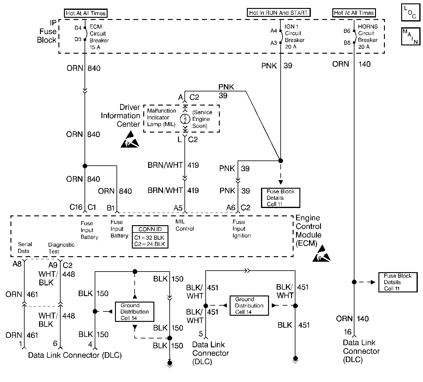
Circuit Description
There should always be a steady MIL when the ignition is ON and engine OFF. The battery ignition voltage is supplied to the lamp. The ECM controls the MIL and turns it ON by providing a ground path through the MIL control circuit.
Diagnostic Aids
If the engine runs OK, check the following items:
| • | Faulty lamp |
| • | MIL control circuit |
If the engine cranks but will not run, refer to ECM Wiring Diagrams and check for the following items:
| • | Blown fuses |
| • | Open in the battery feed circuit |
| • | Open in the ignition feed circuit |
| • | Poor connection to ECM |
Test Description
The numbers below refer to the step numbers on the Diagnostic Table.
-
Using a test lamp connected to 12 volts, probe each of the system ground circuits in order to be sure a good ground is present. Refer to ECM Terminal End View at the end of this section for ECM pin locations of ground circuits.
-
If the fuse is blown, refer to ECM Wiring Diagrams for the complete circuit.
Step | Action | Value(s) | Yes | No |
|---|---|---|---|---|
1 | Did you perform the On-Board Diagnostic (OBD) System Check? | -- | ||
2 | Start the engine. Will the engine start? | -- | ||
3 |
Does the MIL turn ON? | -- | ||
4 |
Did you find a problem? | -- | ||
5 |
Did you find a problem? | -- | ||
6 |
Was a problem found? | -- | ||
7 |
Did you find a problem? | -- | ||
8 |
Did you find a problem? | -- | ||
9 | Repair the MIL control circuit which is shorted to voltage. Is the action complete? | -- | -- | |
10 |
Is the test lamp ON on both circuits? | -- | ||
Was a problem found? | -- | |||
12 |
Did you find a problem? | -- | ||
Is the action complete? | -- | -- | ||
14 | Replace the ECM. Refer to Engine Control Module Replacement Is the action complete? | -- | -- | |
15 |
Does the engine start and continue to run? | -- | ||
16 | Allow the engine to idle until it reaches the normal operating temperature. Are any DTCs stored? | -- | Go to the Applicable DTC Table | System OK |
