GM Service Manual Online
For 1990-2009 cars only

In addition to the ECM, the control module system has the following information sensors and signals:

    • Engine Coolant Temperature (ECT) sensor
    • Manifold Absolute Pressure (MAP) sensor
    • Oxygen Sensor (O2S)
    • Throttle Position (TP) sensor
    • Vehicle Speed Sensor (VSS)
    • Knock Sensor (KS)
    • Neutral switch signal
    • Crank signal
    • Distributor reference signal
    • A/C signal
    • High Idle (if equipped)

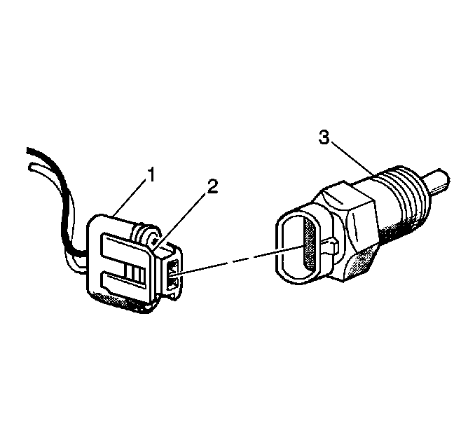
Engine Coolant Temperature (ECT) Sensor


Object Number: 13578  Size: SH
(1)ECT Electrical Connector
(2)Connector Tab
(3)Engine Coolant Temperature (ECT) Sensor

The Engine Coolant Temperature (ECT) sensor is a thermistor (a resistor which changes the value based on the temperature) mounted in the engine coolant stream. Low coolant temperature produces a high resistance (100,000 ohms at -40°C/-40°F) while a high temperature causes a low resistance (70 ohms at 130°C/266°F).

The ECM supplies a 5 volt signal to the ECT sensor through a resistor in the ECM and measures the voltage. The voltage will be high when the engine is cold, and low when the engine is hot. By measuring the voltage, the ECM knows the engine coolant temperature. The engine coolant temperature affects most systems the ECM controls.
Manifold Absolute Pressure (MAP) Sensor


Object Number: 13693  Size: SH
(1)Electrical Connector
(2)Manifold Absolute Pressure (MAP) Sensor

The Manifold Absolute Pressure (MAP) sensor measures the changes in the intake manifold pressure, which result from engine load and speed changes, and converts this to a voltage output.

A closed throttle on engine coastdown will produce a relatively low MAP output, while a wide open throttle will produce a high MAP output. This high output is produced because the pressure inside the manifold is the same as outside the manifold; therefore, 100 percent of the outside air pressure is measured. The MAP sensor reading is the opposite of what you would measure on a vacuum gauge. When the manifold pressure is high, the vacuum is low. The MAP sensor is also used to measure barometric pressure under certain conditions, which allows the ECM to automatically adjust for different altitudes.

The ECM sends a 5 volt reference signal to the MAP sensor. As the manifold pressure changes, the electrical resistance of the MAP sensor also changes. By monitoring the sensor output voltage, the ECM knows the manifold pressure. A higher pressure, low vacuum (high voltage) requires more fuel, while a lower pressure, higher vacuum (low voltage) requires less fuel.

The ECM uses the MAP sensor in order to control the fuel delivery and the ignition timing.

Oxygen Sensor (O2S)


Object Number: 316270  Size: SH

The Oxygen Sensor (O2S) is essentially a small variable battery. The sensor has the ability to produce a low voltage signal that feeds information on the engine exhaust oxygen content to the ECM.

The O2S is constructed from a zirconia/platinum electrolytic element. Zirconia is an electrolyte that conducts electricity under certain chemical conditions. The element is made of a ceramic material and is an insulator when cold. At operating temperature, 315°C (600°F), the element becomes a semiconductor. A platinum coating on the outer surface of the element stimulates further combustion of the exhaust gases right at the surface and this helps keep the element up to the desired temperature. The O2S has an inter cavity which is filled with atmospheric (reference) air. The atmosphere has approximately 2 percent oxygen in it. In the electrical circuit this inter cavity is the positive (+) terminal. The outer surface of the element is exposed to the exhaust gas stream. It is the negative (-) or ground terminal.

Due to the electrolytic properties of the element the oxygen concentration differences between the reference air and the exhaust gases produce small voltages.

A rich exhaust (excessive fuel) has almost no oxygen. When there is a large difference in the amount of oxygen touching the inside and outside surfaces, there is more conduction, and the sensor puts out a voltage signal above 0.6 volt (600 mV). With lean exhaust (excessive oxygen) there is about two percent oxygen in the exhaust. This is a smaller difference in oxygen from the outside surfaces which results in less conduction and a voltage signal below 0.3 volt (300 mV). The ECM monitors and uses the voltages in order to fine tune the air/fuel ratio in order to achieve the ideal mixture desired.

The ECM puts out a reference signal of 0.45 volt (450 mV). The reference signal serves two purposes. The first is to run the engine when it is in an Open Loop mode of operation. When the air/fuel ratio is correct the ECM senses 450 mV. When the engine is operating with a rich air/fuel ratio there is a reduction of free oxygen in the exhaust stream and the O2S voltage rises above the reference voltage.

When the engine runs lean, the voltage drops below the reference voltage due to excess oxygen in the exhaust stream. The O2S provides the feedback information for the Closed Loop operating mode of the fuel delivery system. The O2S indicates to the ECM what is happening in the exhaust. The O2S does not cause things to happen. It is a type of gauge: Low voltage output equals lean mixture equals high oxygen content in the exhaust; high voltage output equals rich mixture equals low oxygen content in the exhaust.

An open O2S, should set a DTC 13. A constant low voltage in the O2S circuit should set a DTC 44. A constant high voltage in the circuit should set a DTC 45. Fuel system problems could set a DTC 44 and 45.

Throttle Position (TP) Sensor


Object Number: 315558  Size: SH

The Throttle Position (TP) sensor (2) is connected to the throttle shaft on the TBI unit (1) with screw assemblies (3). It is a potentiometer with one end connected to 5 volts from the ECM and the other to a ground.

A third wire is connected to the ECM to measure the voltage from the TP sensor. As the throttle valve angle is changed (accelerator pedal moved), the output of the TP sensor also changes. At a closed throttle position, the output of the TP sensor is low (approximately 0.5 volt). As the throttle valve opens, the output increases so that, at wide-open throttle, the output voltage should be approximately 5 volts. By monitoring the output voltage from the TP sensor, the ECM can determine fuel delivery based on throttle valve angle (driver demand).

Vehicle Speed Sensor (VSS)

The Vehicle Speed Sensor (VSS) is a coil mounted on the transmission and a tooth rotor mounted to the output shaft in the transmission. As each rotor tooth nears the coil, the coil produces an AC voltage pulse. As the vehicle speed increases, the number of AC voltage pulses per second increases. The VSS buffer module processes inputs from the VSS and the output signal to the speedometer and the ECM. The VSS buffer module takes the voltage pulses from the VSS and uses them to open and close four solid state output switches in order to ground at a rate proportional to vehicle speed. The VSS buffer module is matched to the vehicle based on final drive ratio and the tire size. It is important to ensure that the correct VSS buffer module is installed in the vehicle if a replacement is necessary.

Knock Sensor (KS)

Located in the engine block, the knock sensor retards the ignition timing during a spark knock condition to allow the ECM to maintain maximum timing advance under most conditions. Refer to Knock Sensor (KS) System Description for further information.

Neutral Switch Signal

The neutral switch, on an automatic transmission vehicle, indicates to the ECM when the transmission is in neutral. The uses this information in order to control the operation of the idle air control and the fuel control.

Crank Signal

The ECM uses this signal in order to tell when the vehicle is in the Starting mode. Refer to Fuel Metering Modes of Operation .

Distributor Reference Signal

The distributor sends a signal to the ECM in order to indicate both engine RPM and crankshaft position. Refer to Distributor Ignition (DI) System Description for further information.

A/C Signal

This signal indicates when the A/C control switch turns ON and the pressure switch closes. The ECM uses this signal in order to adjust the idle speed.