Removal Procedure
- Inspect the fluid level in the brake master cylinder.
- If the brake fluid level is midway between the maximum-full point and the minimum allowable level, no brake fluid needs to be removed from the reservoir before proceeding.
- If the brake fluid level is higher than midway between the maximum-full point and the minimum allowable level, remove brake fluid to the midway point before proceeding.
- Raise and suitably support the vehicle. Refer to Lifting and Jacking the Vehicle in General Information.
- Remove the tire and the wheel assembly. Refer to Tire and Wheel Removal and Installation in Tires and Wheels.
- Compress the front caliper piston.
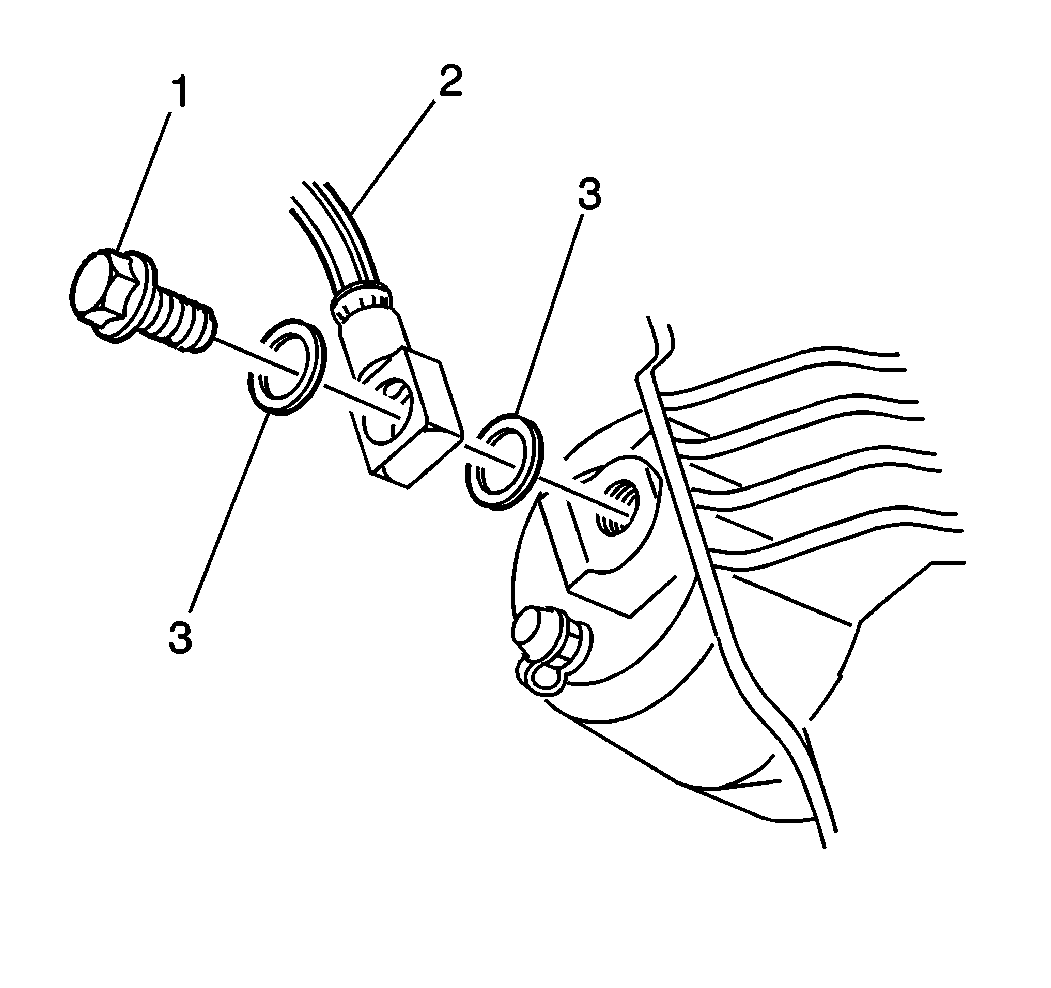
- Remove the brake hose.
- Remove the brake hose to caliper bolt (1) from the brake caliper.
- Remove the brake hose (2) from the brake caliper.
- Remove and discard the 2 copper brake hose gaskets (3). These gaskets may be stuck to the brake caliper and/or the brake hose end.
- Plug the opening in the brake hose in order to prevent excessive brake fluid loss and contamination.
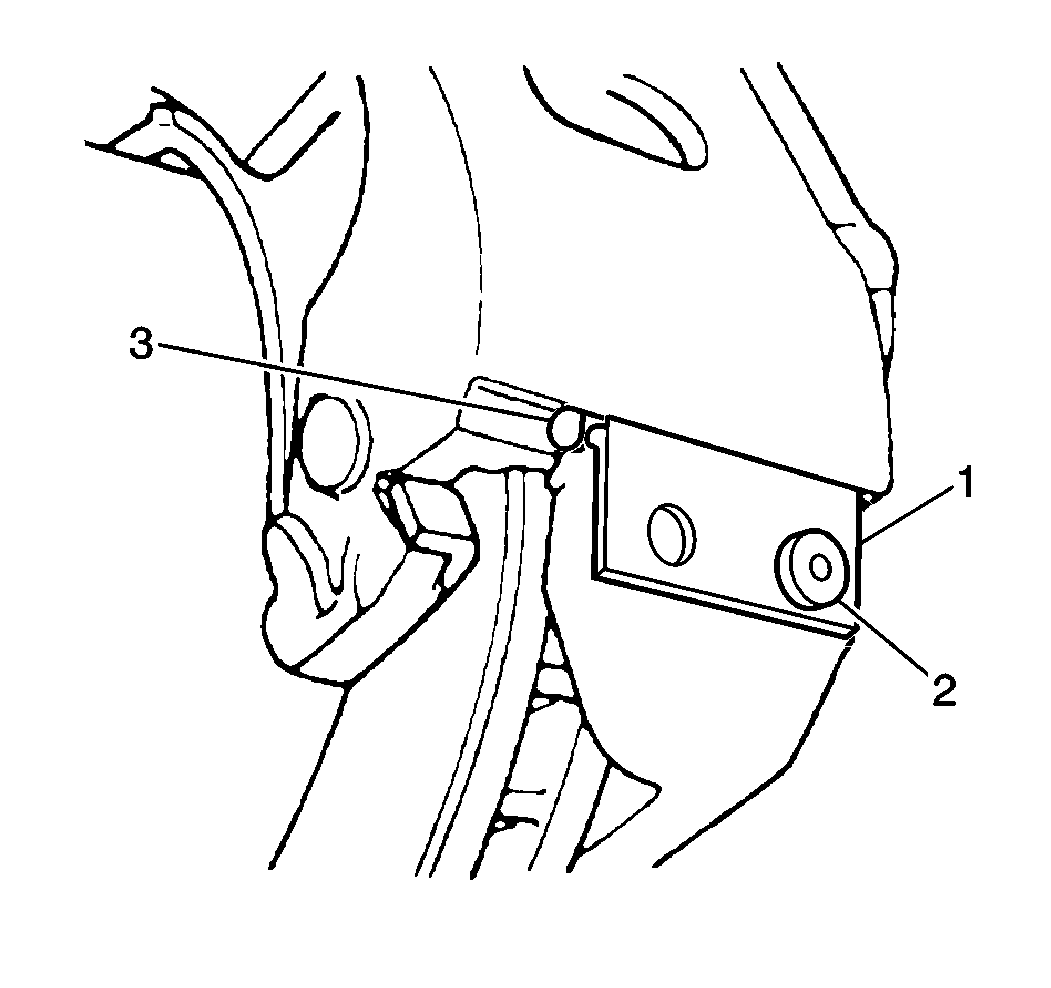
- Remove the caliper lock mounting bolt (2).
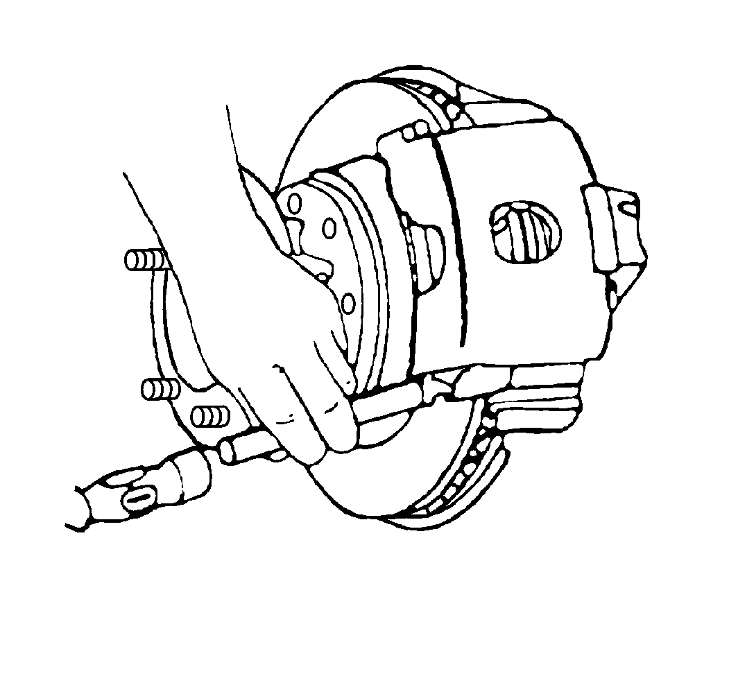
- Remove the support key and the spring using a brass punch and a hammer to drive out the support key.
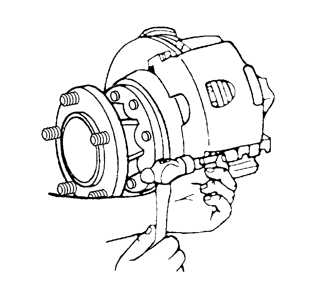
- Remove the caliper assembly.
- Inspect the inside of the caliper assembly for signs of fluid leakage. Refer to Brake Caliper Inspection if any leakage is detected.
- Use a wire brush to remove any corrosion from the machined surfaces of the anchor plate and the caliper.
- Remove the brake pads from the caliper.
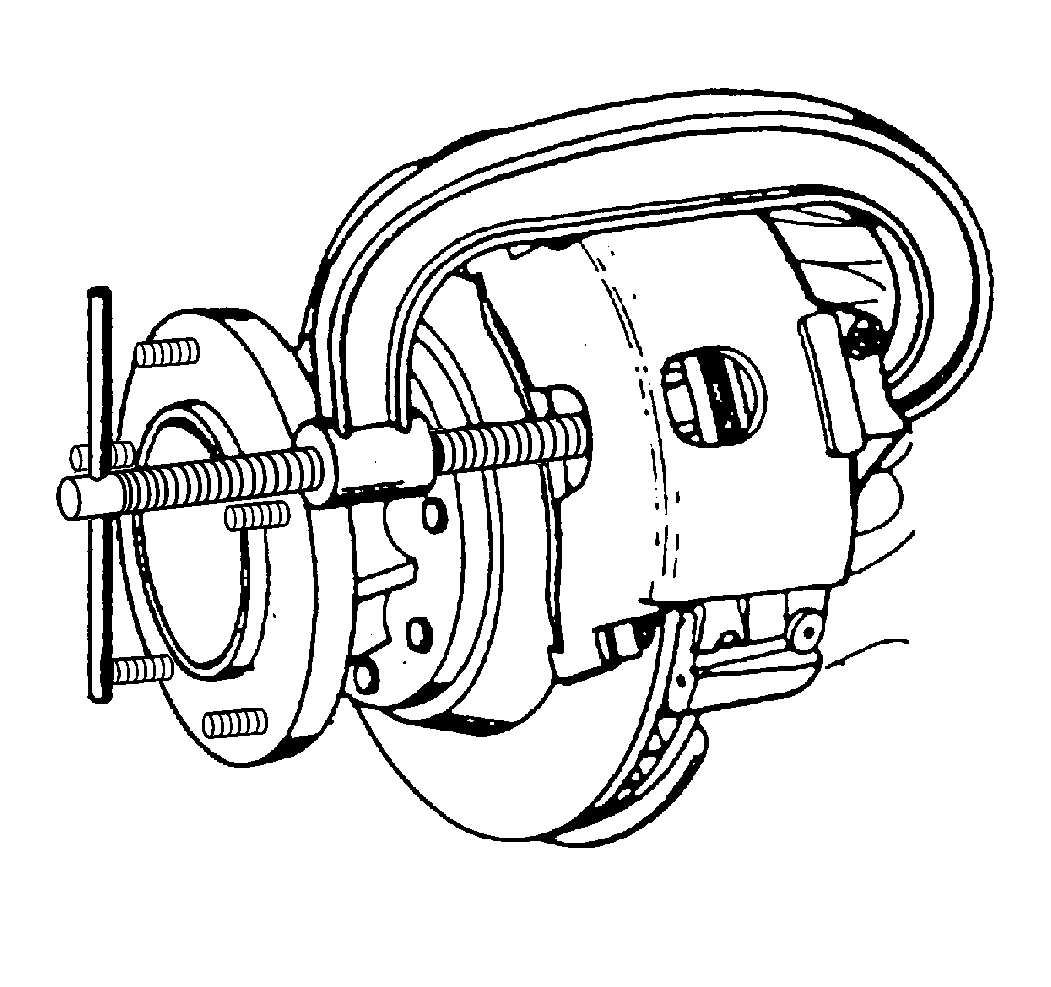
| 6.1. | Install a large C-clamp over the top of the caliper housing and against the back of the outboard pad. |
| 6.2. | Slowly tighten the C-clamp until the piston pushes into the caliper bore enough to slide the caliper off the rotor. |
| 6.3. | Remove the C-clamp from the caliper. |
Do not pinch off the brake hose with any tools.
Installation Procedure
- Apply high temperature silicone brake lubricant to the caliper and the anchor plate sliding surfaces. DO NOT apply lubricant to the brake pad hardware.
- Install the brake pads to the caliper. Refer to Front Disc Brake Pads Replacement .
- Install the caliper assembly to the mounting plate.
- Inspect the brake caliper/mounting plate wear adjustment. Refer to Brake Caliper/Mounting Plate Wear Adjustment .
- Install the spring and the support key using a brass punch and a hammer to drive the support key into place.
- Install the caliper lock mounting bolt (2). The boss on the bolt must fit into the circular cutout in the key.
- Remove the rubber cap or plug from the exposed brake pipe fitting end.
- Assemble the NEW copper brake hose gaskets (3), and the brake hose bolt (1) to the brake hose (2).
- With the weight of the vehicle on the suspension, install the brake hose to caliper bolt (1) and NEW washers (3) to the brake caliper.
- Ensure that the brake hose does not make contact with any part of the suspension. Check the hose in extreme right and left turn conditions. If the hose makes contact, remove the hose and correct the condition.
- Fill the brake master cylinder to the proper level. Refer to Master Cylinder Reservoir Filling in Hydraulic Brakes.
- Bleed the hydraulic brake system. Refer to Hydraulic Brake System Bleeding in Hydraulic Brakes.
- Install the tire and the wheel assembly. Refer to Tire and Wheel Removal and Installation in Tires and Wheels.
- Lower the vehicle.
Important: Do not use NEVER SEIZE type products on the caliper V-ways and/or anchor plate guide way surfaces.

Notice: Use the correct fastener in the correct location. Replacement fasteners must be the correct part number for that application. Fasteners requiring replacement or fasteners requiring the use of thread locking compound or sealant are identified in the service procedure. Do not use paints, lubricants, or corrosion inhibitors on fasteners or fastener joint surfaces unless specified. These coatings affect fastener torque and joint clamping force and may damage the fastener. Use the correct tightening sequence and specifications when installing fasteners in order to avoid damage to parts and systems.
Tighten
Tighten the caliper lock mounting bolts to 20 N·m (15 lb ft).

Important: Install NEW copper brake hose gaskets.
Important: The hose must not be twisted. Make sure the hose is not in contact with any suspension component.
Tighten
Tighten the brake hose bolt to 45 N·m (33 lb ft).
