Cylinder Head Replacement Left Side
Removal Procedure
- Disconnect the battery negative cable. Refer to Battery Replacement .
- Drain the engine coolant. Refer to Cooling System Draining and Filling .
- Remove the air cleaner outlet duct from the throttle body. Refer to Intake Air Resonator Replacement .
- Remove the A/C hose from the accumulator and the A/C compressor and move aside, if equipped. Refer to Compressor Hose Assembly Replacement .
- Disconnect the wire connectors to the A/C compressor, if equipped.
- Remove the engine wiring harness from the accelerator control cable bracket.
- Remove the bolt and the accelerator control cable bracket from the power steering pump mounting bracket.
- Remove the upper fan shroud. Refer to Engine Coolant Fan Shroud Replacement .
- Remove the engine cooling fan. Refer to Fan Clutch Replacement .
- Remove the drive belt. Refer to Drive Belt Replacement .
- Remove the power steering pump pulley. Refer to Power Steering Pump Replacement .
- Remove the bolts holding the power steering pump to the power steering pump mounting bracket.
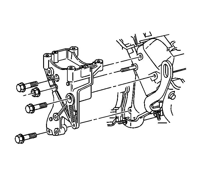
- Remove the three bolts and nut holding the power steering pump mounting bracket to the engine.
- Slide the power steering pump mounting bracket off of the stud and the power steering pump.
- Remove the power steering pump mounting bracket stud from the cylinder head.
- Remove the intake manifold. Refer to Intake Manifold Replacement .
- Remove the exhaust manifold. Refer to Exhaust Manifold Replacement .
- Remove the valve pushrods. Refer to Valve Rocker Arm and Push Rod Replacement .
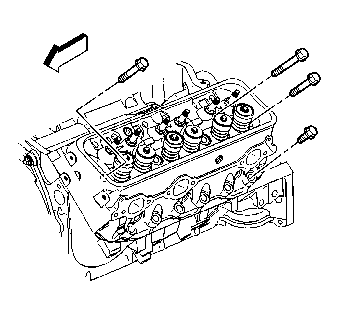
- Remove and discard the cylinder head bolts.
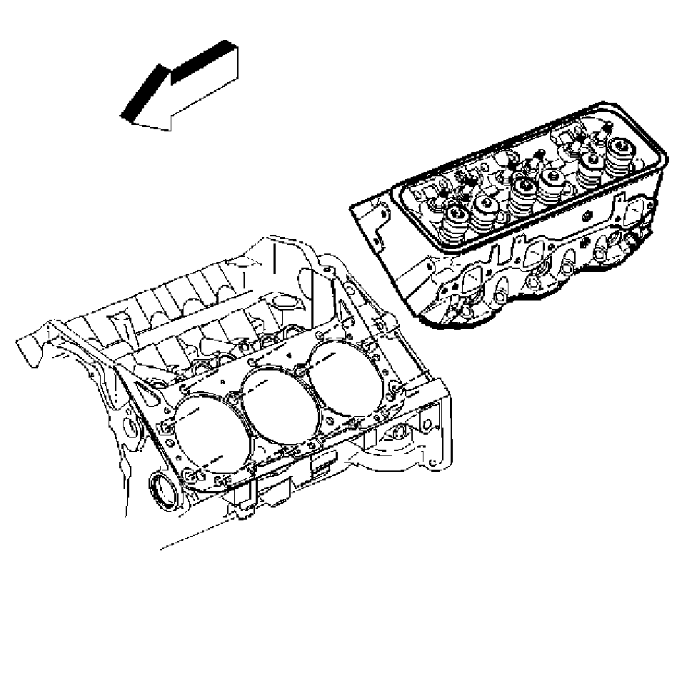
- Remove the cylinder head.
- Clean all surfaces. Refer to Cylinder Head Cleaning and Inspection .
The A/C compressor can be left on the power steering pump mounting bracket.
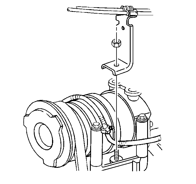
Leave the accelerator control cable and the cruise control cable on the bracket.
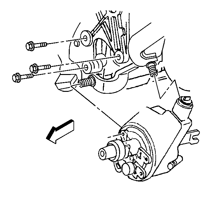
The power steering pump can remain on the engine.
Installation Procedure
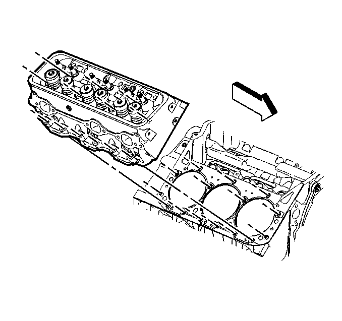
- Install the cylinder head. Refer to Cylinder Head Installation .
- Install the valve pushrods. Refer to Valve Rocker Arm and Push Rod Replacement .
- Install the exhaust manifold. Refer to Exhaust Manifold Replacement .
- Install the intake manifold. Refer to Intake Manifold Replacement .
- Install the power steering pump mounting bracket stud in the cylinder head.
- Slide the power steering pump mounting bracket onto the stud and the power steering pump.
- Install the three bolts and the nut for the power steering pump mounting bracket.
- Install the three bolts holding the power steering pump to the power steering pump mounting bracket.
- Install the power steering pump pulley. Refer to Power Steering Pump Replacement .
- Install the drive belt. Refer to Drive Belt Replacement .
- Install the engine cooling fan. Refer to Fan Clutch Replacement .
- Install the upper fan shroud. Refer to Engine Coolant Fan Shroud Replacement .
- Install the accelerator control cable to the power steering pump mounting bracket.
- Install the engine wiring harness to the accelerator control cable bracket.
- Install the A/C hose to the accumulator and the A/C compressor, if equipped. Refer to Compressor Hose Assembly Replacement .
- Fill the engine coolant system. Refer to Cooling System Draining and Filling .
- Connect the battery negative cable. Refer to Battery Replacement .
- Install the air cleaner outlet duct onto the throttle body. Refer to Intake Air Resonator Replacement .
Notice: Refer to Fastener Notice in the Preface section.

Tighten
Tighten the power steering pump mounting bracket stud to 20 N·m (15 lb ft).
Tighten
Tighten the power steering pump mounting bracket bolts and nut to 41 N·m (30 lb ft).

Tighten
Tighten the power steering pump bolts to 50 N·m (37 lb ft).

Tighten
Tighten the accelerator control cable bolt to 17 N·m (13 lb ft).
Cylinder Head Replacement Right Side
Removal Procedure
- Disconnect the battery negative cable. Refer to Battery Replacement .
- Drain the engine coolant. Refer to Cooling System Draining and Filling .
- Remove the air cleaner outlet duct from the throttle body. Refer to Intake Air Resonator Replacement .
- Remove the engine cooling fan assembly. Refer to Fan Clutch Replacement .
- Remove the intake manifold. Refer to Intake Manifold Replacement .
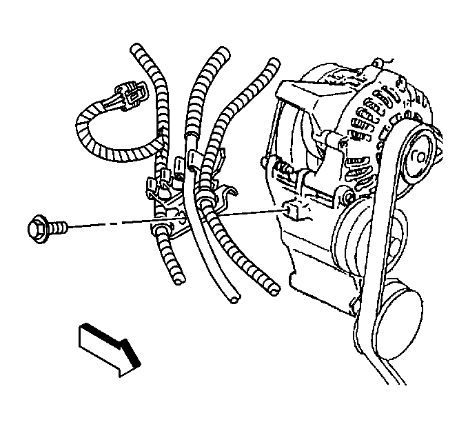
- Disconnect the wires from the generator.
- Remove the bolt and the HVAC hose bracket from the generator mounting bracket.
- Remove the drive belt tensioner. Refer to Drive Belt Tensioner Replacement .
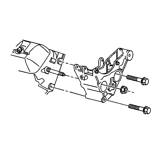
- Remove the generator mounting bracket two bolts and nut.
- Remove the generator mounting bracket.
- Remove the generator mounting bracket stud from the cylinder head.
- Remove the exhaust manifold. Refer to Exhaust Manifold Replacement .
- Remove the valve pushrods. Refer to Valve Rocker Arm and Push Rod Replacement .
- Remove and discard the cylinder head bolts.
- Remove the cylinder head.
- Clean all surfaces. Refer to Cylinder Head Cleaning and Inspection .
The generator can remain on the generator mounting bracket.
Installation Procedure
- Install the cylinder head. Refer to Cylinder Head Installation .
- Install the valve pushrods. Refer to Valve Rocker Arm and Push Rod Replacement .
- Install the exhaust manifold. Refer to Exhaust Manifold Replacement .
- Install the generator mounting bracket stud to the cylinder head.
- Install the generator mounting bracket.
- Install the generator mounting bracket two bolts and the nut.
- Install the drive belt tensioner. Refer to Drive Belt Tensioner Replacement .
- Install the bolt and the HVAC hose bracket to the generator mounting bracket.
- Connect the wires to the generator.
- Install the intake manifold. Refer to Intake Manifold Replacement .
- Install the engine cooling fan. Refer to Fan Clutch Replacement .
- Install the air cleaner outlet duct onto the throttle body. Refer to Intake Air Resonator Replacement .
- Fill the engine coolant system. Refer to Cooling System Draining and Filling .
- Connect the battery negative cable. Refer to Battery Replacement .

Notice: Refer to Fastener Notice in the Preface section.

Tighten
Tighten the stud to 20 N·m (15 lb ft).
Tighten
Tighten the generator mounting bracket two bolts and the nut to 41 N·m (30 lb ft).

Tighten
Tighten the HVAC hose bracket bolt to 30 N·m (22 lb ft).
