Removal Procedure
Refer to the following transmission component locator graphics as needed:


- Disconnect the battery negative cable assembly from the battery
negative terminal. Refer to
Caution: Unless directed otherwise, the ignition and start switch must be in the OFF or LOCK position, and all electrical loads must be OFF before servicing
any electrical component. Disconnect the negative battery cable to prevent an electrical spark should a tool or equipment come in contact with an exposed electrical terminal. Failure to follow these precautions may result in personal injury and/or damage to
the vehicle or its components.
- Raise the vehicle. Refer to Vehicle Lifting and Jacking in General
Information.
- Support the vehicle with safety stands.
- Lower the transmission, if required for clearance.
- Remove the transmission oil pan and the transmission oil filter.
Refer to
Automatic Transmission Fluid and Filter Replacement
Important: Use a cap to cover electrical pins at the case connection.
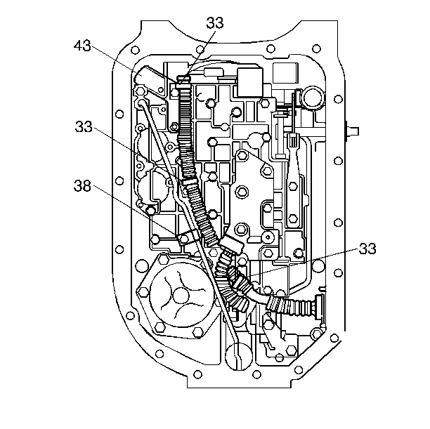
- Remove all electrical connectors from the electrical components.
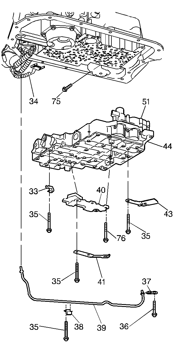
- Remove twenty-one bolts from the valve body assembly and the manual
detent spring assembly.
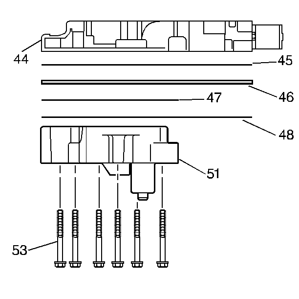
- Remove six bolts from the pressure manifold assembly. Use an 8 mm
socket.
- Ensure the five O-rings are attached to the pressure manifold
assembly.
- Remove the following parts:
| 10.1. | The three wiring clips |
| 10.2. | The fluid level indicator stop |
| 10.3. | One bolt using a 10 mm socket |
| 10.5. | The lube pipe retainer |
- Remove the following parts:
| 11.1. | The control valve assembly including the accumulator housing assembly |
| 11.2. | The valve body gaskets |
| 11.4. | The accumulator gasket |
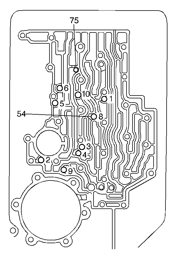
- Ensure there is no gasket material left on the case surface.
- Remove eight check balls from case passages.
- Remove the PWM (Pulse Width Modulation) solenoid screen.
- Clean the control valve assembly and accumulator housing thoroughly
in clean solvent.
- Use compressed air in order to dry the control valve assembly.
- Disassemble the control valve assembly and the accumulator housing.
Refer to
Control Valve Body Assembly Removal
.
The use of a honing stone, fine sandpaper, or crocus cloth is not recommended
for servicing stuck valves. All valve lands have sharply machined corners
that are necessary to cleaning the bore. If these corners are rounded, foreign
material could wedge between the valve and the bore causing the valve to stick.
If a valve must be cleaned, use micro fine lapping compound (900 grit or finer).
Too much lapping of the valve will cause excessive clearances and increase
the chance of a valve not operating.


