Removal Procedure
Caution: Unless directed otherwise, the ignition and start switch must be in the OFF or LOCK position, and all electrical loads must be OFF before servicing
any electrical component. Disconnect the negative battery cable to prevent an electrical spark should a tool or equipment come in contact with an exposed electrical terminal. Failure to follow these precautions may result in personal injury and/or damage to
the vehicle or its components.
- Disconnect
the negative battery cable.
- Remove the valve rocker arm cover from the cylinder head. Refer
to
Valve Rocker Arm Cover Replacement
.
- Rotate the crankshaft until both the intake and exhaust valves
are closed before applying the compressed air into the cylinder being serviced.
- Remove the valve rocker arm from the cylinder head. Refer to
Valve Rocker Arm and Push Rod Replacement
.
- Remove the valve push rod from the cylinder head. Refer to
Valve Rocker Arm and Push Rod Replacement
.
- Remove the spark plugs from the cylinder head. Refer to
Spark Plug Replacement
in Engine
Electrical.

- Remove the valve keepers
as follows:
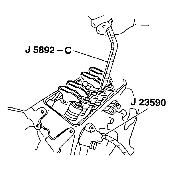
| 7.1. | Install the J 23590
into the spark plug hole. |
| 7.2. | Apply compressed air into the cylinders in order to hold the valves
closed. |
| 7.3. | Lightly tap the valve spring retainer to loosen the valve keepers. |
| 7.4. | Install the J 5892-C
to the cylinder head. |
| 7.5. | Install the valve rocker arm bolt. |
| | Important: Tighten the valve rocker arm bolt enough to hold J 5892-C
in place while compressing the valve
and valve spring assembly.
|
| 7.6. | Use the J 5892-C
to
compress the valve spring assembly. |
| 7.7. | Remove the valve keepers. |
| | Important: Do not release the compressed air from the cylinder being worked on.
The valve will fall into the cylinder bore.
|
| 7.8. | Carefully release the spring tension and remove the J 5892-C
. |
| 7.9. | Remove the J 5892-C
from the cylinder head. |

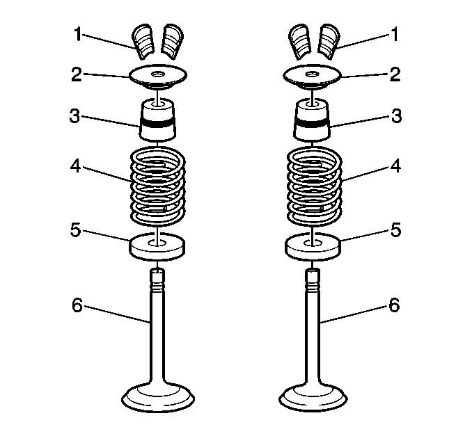
- Remove the valve spring
retainer (2) and the valve spring (4) from the cylinder head.
- Remove the valve stem oil seal (3) from the valve guide.
Installation Procedure
Tools Required
- Install the valve stem oil seal (3) to the valve guide.
- Install the valve spring (4) and the valve spring retainer (2).

- Install the valve keepers
(1) to the valve:
- With the compressed air still applied, use the J 5892-C
to compress the valve spring assembly.

- Install the valve keepers
to the valve being worked on. Apply a small amount of clean grease to aid
in holding the valve keepers in place.
- Carefully release the tension on the valve spring assembly. Make
sure the valve keepers do not move while releasing the tension.
- Remove the J 5892-C
from the valve assembly.
- Carefully release the compressed air from the cylinder being worked
on.
- Install the spark plugs to the cylinder head into the cylinder
being serviced. Refer to
Spark Plug Replacement
.
- Install the push rods into the cylinder head.
- Install the valve rocker arms to the cylinder head for the cylinder
being serviced. Refer to
Valve Rocker Arm and Push Rod Replacement
.
- Install the valve rocker arm cover to the cylinder head. Refer
to
Valve Rocker Arm Cover Replacement
.
Caution: Unless directed otherwise, the ignition and start switch must be in the OFF or LOCK position, and all electrical loads must be OFF before servicing
any electrical component. Disconnect the negative battery cable to prevent an electrical spark should a tool or equipment come in contact with an exposed electrical terminal. Failure to follow these precautions may result in personal injury and/or damage to
the vehicle or its components.
- Connect the
negative battery cable.


