Removal Procedure
- Disconnect the negative battery cable.
Refer to
Caution: Unless directed otherwise, the ignition and start switch must be in the OFF or LOCK position, and all electrical loads must be OFF before servicing
any electrical component. Disconnect the negative battery cable to prevent an electrical spark should a tool or equipment come in contact with an exposed electrical terminal. Failure to follow these precautions may result in personal injury and/or damage to
the vehicle or its components.
in General
Information.
- Drain about 2/3 of the brake fluid from the reservoir.
- Raise the vehicle. Support the vehicle with safety stands.
- Remove the tires and the wheels. Refer to Wheel Removal and Tire
Mounting and Dismounting in Tires and Wheels
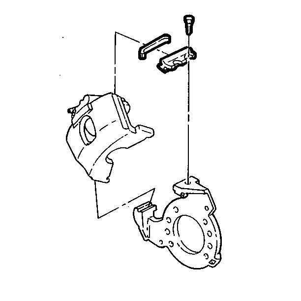
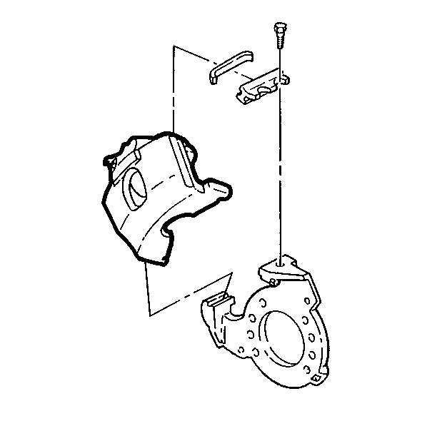
- Remove the key retaining bolt.
- Remove the key and the spring using a brass punch.
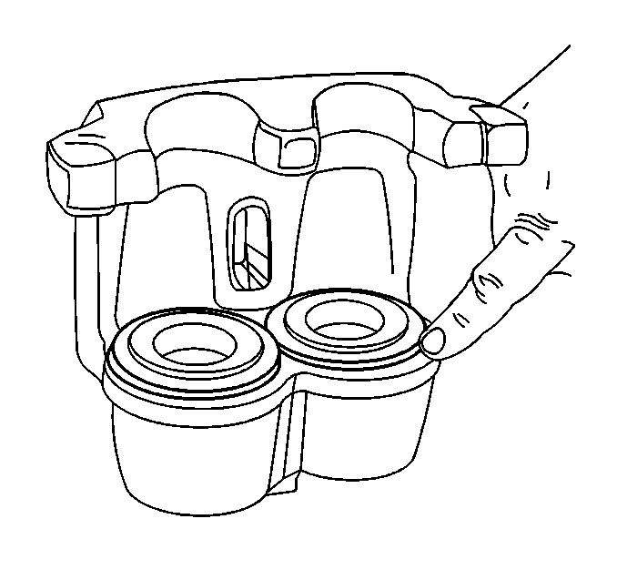
- Compress the caliper pistons.
| 7.1. | Use a C-clamp between the inner caliper housing and the outer
lining or use a screwdriver in order to pry between the outer caliper housing
and the outer lining. |
| 7.2. | Watch for possible fluid overflow at the reservoir during this
step. |
| 7.3. | The inner lining may stay on the anchor plate (Bendix brake) (front
disc brakes). |
- Disconnect the brake hose
| 8.1. | Clean the area around the hose on the caliper. |
| 8.2. | Cap or tape the fitting in order to prevent dirt from entering
the brake hose. |
Inspection Procedure
- Inspect the inside of the caliper for
hydraulic fluid leaks. Overhaul the caliper if leaks are found.
- Inspect the piston seal for leaks and fluid around the boot, the
shield, and the inboard lining.
- Inspect the piston dust boots for burns, tears, or other damage.
Overhaul the caliper if damage is found.
- Inspect the guideway surfaces on the caliper and the anchor plate.
- Inspect the dust shields. Replace the shields if they are loose.
- Inspect under the boots for leakage. Overhaul the caliper if leakage
is present.
Installation Procedure
- Compress the caliper piston to the bottom
of the bores.
| 1.1. | If the piston cannot be pushed by hand, place a small block of
wood over the pistons and boots. Use a C-clamp around the wood block and the
caliper housing in order to push in the pistons. |
| 1.2. | Do not drive the pistons in with a mallet or metal tools. |
| 1.3. | Lubricate the guideway and the anchor plate with lubricant (P/N
18010909). |
- Install the caliper.
Notice: Make sure the brake hose is not twisted or kinked after
installation. Damage to the hose could result.
- Connect the brake hose.
Tighten
Tighten the brake hose to the caliper fitting to 13 N·m
(88 lb ft).
Notice: Use the correct fastener in the correct location. Replacement fasteners
must be the correct part number for that application. Fasteners requiring
replacement or fasteners requiring the use of thread locking compound or sealant
are identified in the service procedure. Do not use paints, lubricants, or
corrosion inhibitors on fasteners or fastener joint surfaces unless specified.
These coatings affect fastener torque and joint clamping force and may damage
the fastener. Use the correct tightening sequence and specifications when
installing fasteners in order to avoid damage to parts and systems.
- Install the retaining key and the spring
in the guideway.
| • | Tap the key into place using a brass punch and a light hammer.
The hole in the key should line up with the threaded hole in the housing. |
- Install the retaining bolt.
- The bolt boss must fit in the circular hole in the key.
Tighten
Tighten the retaining bolt to 40 N·m (30 lb ft).
- Fill the reservoir with brake fluid. Refer to Filling the Master
Cylinder Reservoir in Hydraulic Brakes.
- Bleed the hydraulic brake system. Refer to Pressure Brake System
Bleeding in Hydraulic Brakes.
- Install the tires and wheels. Refer to Wheel Removal and Tire
Mounting and Dismounting in Tires and Wheels.
- Lower the vehicle.
- Connect the negative battery cable.
