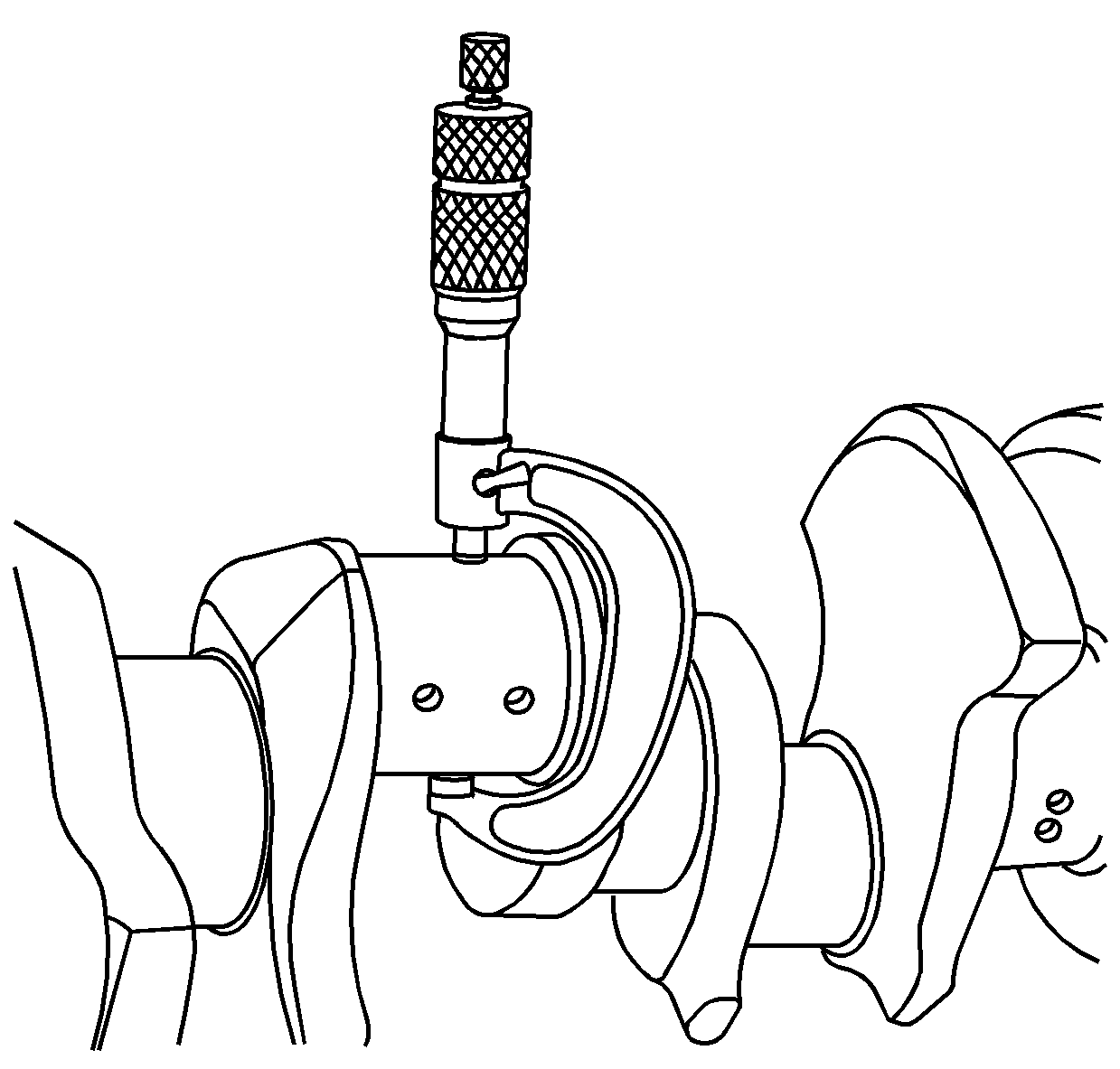
- Clean the crankshaft with solvent. Do not scratch the bearing journals.
- Remove all of the sludge from the oil passages with compressed air.
- Clean the crankshaft bearings. Wipe free of oil with a soft cloth.
- Inspect the crankshaft for cracks as follows:
Important: Replace the clutch pilot bearing located in the end of the crankshaft, anytime a manual transmission or clutch is removed. A worm clutch pilot bushing will not properly support the manual transmission input shaft when the clutch is released.
| • | Use the magnaflux method if available. |
| • | Inspect the crankshaft, the crankshaft bearing journals, and the thrust surfaces for scoring, nicks, or damage caused by lack of lubrication. |
| • | Inspect the crankshaft bearings for scoring or other damage. In general, the lower crankshaft bearings, except the #1 bearing, show the greatest wear and distress from fatigue. Upon inspection, if a lower crankshaft bearing is suitable for reuse, it can be assumed that the upper crankshaft bearing is also satisfactory. If a lower crankshaft bearing shows evidence of wear or damage, both the upper and the lower crankshaft bearings must be replaced. |
Crankshaft Bearing Cap Replacement Procedure
- Install the new crankshaft bearing cap and the bolts. Ensure that the arrow on the crankshaft bearing cap is facing the front of the engine.
- Measure the crankshaft bearing bore vertical inside diameter. This dimension should be the same as the other crankshaft bearing bore vertical inside diameters.
- Mark the new bearing cap for proper location.
- Remove the bearing cap bolts and bearing cap.
Notice: In order to prevent the possibility of cylinder block or crankshaft bearing cap damage, the crankshaft bearing caps are tapped into the cylinder block cavity using a brass, lead, or a leather mallet before the attaching bolts are installed. Do not use attaching bolts to pull the crankshaft bearing caps into the seats. Failure to use this process may damage a cylinder block or a bearing cap.
Important: Tighten inside bearing cap bolts first and outside bearing cap bolts last.
Tighten
Tighten the bolts to 135 N·m (100 lb ft).
Notice: Use the correct fastener in the correct location. Replacement fasteners must be the correct part number for that application. Fasteners requiring replacement or fasteners requiring the use of thread locking compound or sealant are identified in the service procedure. Do not use paints, lubricants, or corrosion inhibitors on fasteners or fastener joint surfaces unless specified. These coatings affect fastener torque and joint clamping force and may damage the fastener. Use the correct tightening sequence and specifications when installing fasteners in order to avoid damage to parts and systems.
Bearing Clearance Measuring Procedure
The crankshaft bearings are of the precision insert type and do not use shims for adjustment. If the clearances are excessive, the new upper and the lower bearings will be required. The service bearings are available in the standard size and an undersize.
| • | 0.001 in |
| • | 0.002 in |
| • | 0.010 in |
| • | 0.020 in |
The selective fitting of the crankshaft bearings are necessary in production in order to obtain close tolerances. For this reason, you may use one-half of a standard crankshaft bearing with one-half of a undersize crankshaft bearing.
In order to determine the correct replacement bearing size, the bearing clearance must be measured accurately. Either the micrometer or plastic gauge method may be used, however, the micrometer method gives more reliable results and is preferred.
Micrometer Method for Crankshaft Bearings
- Measure the crankshaft main journal diameter with a micrometer in several places, approximately 90 degrees apart, and average the measurements.
- Compute the taper and the out of round. Refer to Engine Mechanical Specifications for allowable limits.
- Install the crankshaft bearings into the crankshaft bearing cap and the engine block.
- Install the crankshaft bearing caps and the bolts. Ensure that the arrows on the crankshaft bearing caps are facing the front of the engine.
- Measure the bearing inside diameter (ID) using an inside micrometer.
- Compare the crankshaft bearing clearance specifications. Refer to Engine Mechanical Specifications .
- If the bearing clearance is within specifications, the bearing is satisfactory. If the clearance is not within specifications, replace the bearing. Always replace both the upper and the lower bearings as a unit.
- A standard or undersize bearing combination may result in the proper clearance. If the proper bearing clearance cannot be achieved using the standard or the undersize bearings, it will be necessary to replace or repair the crankshaft.
Notice: Do not shim, scrape, or file bearing inserts. Do not touch the bearing surface of the insert with bare fingers. Skin oil and acids will etch the bearing surface.

Notice: In order to prevent the possibility of cylinder block or crankshaft bearing cap damage, the crankshaft bearing caps are tapped into the cylinder block cavity using a brass, lead, or a leather mallet before the attaching bolts are installed. Do not use attaching bolts to pull the crankshaft bearing caps into the seats. Failure to use this process may damage a cylinder block or a bearing cap.
Important: Tighten inside bearing cap bolts first and outside bearing cap bolts last.
Tighten
Tighten the bolts to 135 N·m (100 lb ft).
Micrometer Method for Connecting Rod Bearings
- Measure the crankpin diameter with a micrometer in several places, approximately 90 degrees apart, and average the measurements.
- Compute the taper and the out of round. Refer to Engine Mechanical Specifications for allowable limits.
- Install the connecting rod bearings into the connecting rod bearing cap and the connecting rod.
- Install the connecting rod bearing caps and the nuts.
- Measure the bearing inside diameter (ID) using an inside micrometer.
- Compare the connecting rod bearing clearance specifications. Refer to Engine Mechanical Specifications .
- If the bearing clearance is within specifications, the bearing is satisfactory. If the clearance is not within specifications, replace the bearing. Always replace both the upper and the lower bearings as a unit.
- A standard or undersize bearing combination may result in the proper clearance. If the proper bearing clearance cannot be achieved using the standard or the undersize bearings, it will be necessary to replace or repair the crankshaft.
Notice: Do not shim, scrape, or file bearing inserts. Do not touch the bearing surface of the insert with bare fingers. Skin oil and acids will etch the bearing surface.

Tighten
Tighten the nuts to 61 N·m (45 lb ft).
Notice: Use the correct fastener in the correct location. Replacement fasteners must be the correct part number for that application. Fasteners requiring replacement or fasteners requiring the use of thread locking compound or sealant are identified in the service procedure. Do not use paints, lubricants, or corrosion inhibitors on fasteners or fastener joint surfaces unless specified. These coatings affect fastener torque and joint clamping force and may damage the fastener. Use the correct tightening sequence and specifications when installing fasteners in order to avoid damage to parts and systems.
Plastic Gauge Method
Plastic gauge method is covered in Crankshaft and Bearing Installation and Piston, Connecting Rod, and Bearing Installation procedures.
Crankshaft Runout Measuring Procedure
Tools Required
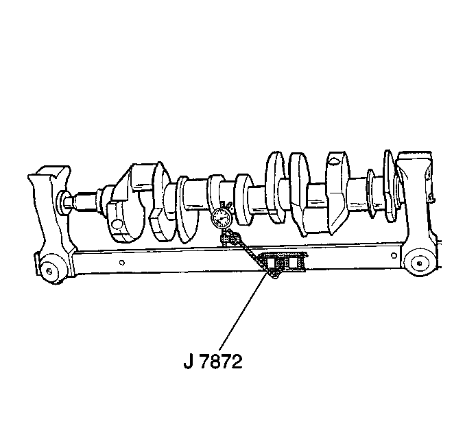
J 7872 Magnetic Base Dial Indicator
- Mount the crankshaft in V-blocks at the crankshaft journals 1 and 5.
- Use the J 7872 in order to measure crankshaft runout. Crankshaft runout should not exceed 0.051 mm (0.002 in).

