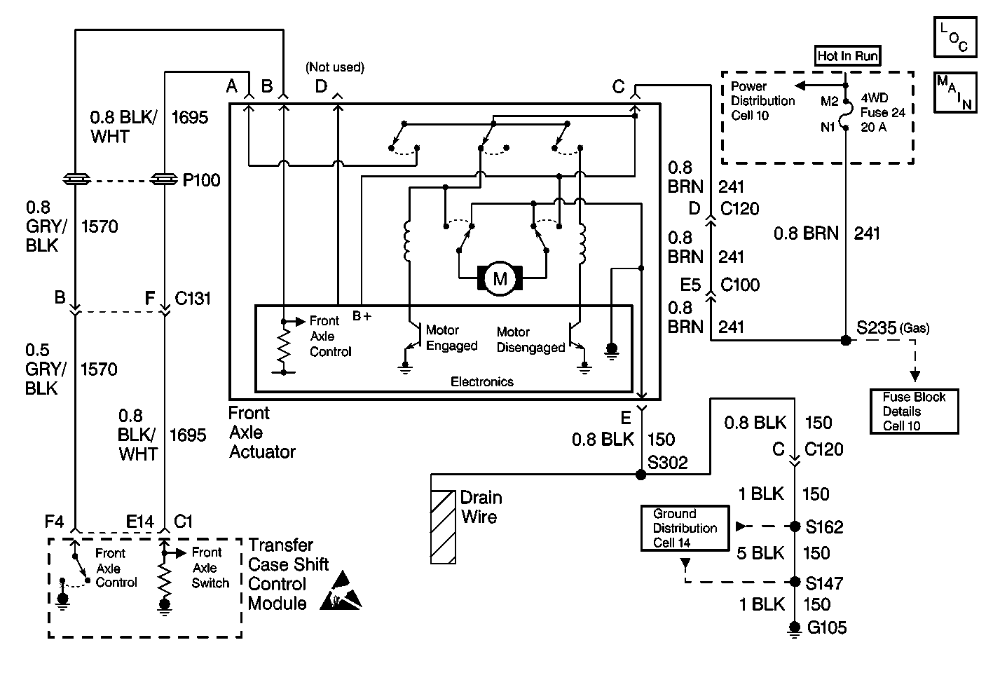
Test Description
The number(s) below refer to the step number(s) on the diagnostic table.
-
This step determines if the front axle actuator has a good power and ground supplied to it.
-
This step determines if the transfer case shift control module is providing the ground signal to the front axle actuator through terminal B in order to drive the front axle actuator motor.
-
This step determines if the transfer case shift control module is able to sense voltage on CKT 1695.
Step | Action | Value(s) | Yes | No |
|---|---|---|---|---|
1 | Was the Transfer Case Diagnostic System Check performed? | -- | Go to Step 2 | |
2 |
Does the Front Axle Switch display change from Unlocked to Locked? | -- | Go to Step 6 | Go to Step 3 |
Is the voltage within the value specified? | 9-14 V | Go to Step 4 | Go to Step 9 | |
Is the voltage reading within the specified values? | 9-14 V | Go to Step 5 | Go to Step 14 | |
Does the Scan Tool show the Front Axle Switch status Locked? | -- | Go to Step 17 | Go to Step 7 | |
6 | Inspect the front axle for mechanical concerns, if no mechanical concerns are present replace the Front Axle Actuator. Is the repair complete? | -- | Go to Step 19 | -- |
7 |
Is the resistance reading within the specified values? | 0-0.5 V | Go to Step 16 | Go to Step 8 |
8 | Repair open in CKT 1695. Refer to Wiring Repairs in Wiring Systems. Is the repair complete? | -- | Go to Step 19 | -- |
9 |
Is the voltage reading within the specified values? | 9-14 V | Go to Step 10 | Go to Step 11 |
10 | Repair open in CKT 2150. Refer to Wiring Repairs in Wiring Systems. Is the repair complete? | -- | Go to Step 19 | -- |
11 | Inspect the 4WD fuse in CKT 241 for continuity. Is the fuse good? | -- | Go to Step 12 | Go to Step 13 |
12 | Repair open in CKT 241. Refer to Wiring Repairs in Wiring Systems. Is the repair complete? | -- | Go to Step 19 | -- |
13 |
Is the fuse good? | -- | Go to Step 19 | Go to Step 18 |
14 |
Is the resistance reading within the specified values? | 0-5 ohms | Go to Step 16 | Go to Step 15 |
15 | Repair open in CKT 1296. Refer to Wiring Repairs in Wiring Systems. Is the repair complete? | -- | Go to Step 19 | -- |
16 | Replace the transfer case shift control module. Refer to Transfer Case Shift Control Module Replacement . Is the action complete? | -- | Go to Step 19 | -- |
17 | Replace the front axle actuator. Refer to Electric Motor Actuator Replacement . Is the action complete? | -- | Go to Step 19 | -- |
18 | Repair short to ground in CKT 241. Refer to Wiring Repairs in Wiring Systems. Is the repair complete? | -- | Go to Step 19 | -- |
19 |
Have all the ATC components been reconnected and properly mounted? | -- | Go to Step 20 | -- |
20 | Clear all ATC DTCs. Have all the ATC DTCs been cleared? | -- | -- |
