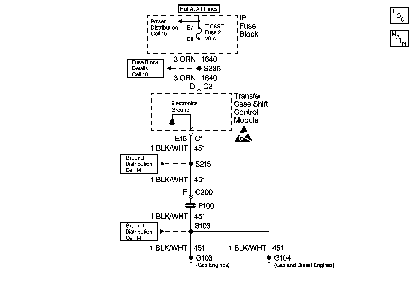
Circuit Description
The direct battery supply line (circuit 1640) provides the power to the module and motor circuitry.
This DTC detects a intermittent absence of battery voltage at the module when the module sees an ignition on voltage.
Conditions for Setting the DTC
The transfer case shift control module did not power up 8 out of the last 19 ignition cycles.
Action Taken When the DTC Sets
There are no default actions associated with this DTC. The SERVICE AWD/4WD lamp will not be latched on.
Conditions for Clearing the DTC
| • | Current DTC |
| The transfer case shift control module will clear the DTC if the condition for setting the DTC no longer exists. |
| • | History DTC |
| - | Once 100 consecutive ignition cycles without a fault present. |
| - | You issue a scan tool CLEAR CODES command. |
Test Description
The number(s) below refer to the step number(s) on the diagnostic table.
-
This step determines if an intermittent open exists in circuit 1640.
-
This step determines if an intermittent open exists in circuit 1640.
Step | Action | Value(s) | Yes | No |
|---|---|---|---|---|
1 | Was the Transfer Case Diagnostic System Check performed? | -- | Go to Step 2 | |
2 | Inspect the ATC Fuse in the Underhood Bussed Electrical Center. Is the fuse good? | -- | Go to Step 9 | Go to Step 3 |
3 |
Is the fuse good? | -- | Go to Step 4 | Go to Step 9 |
4 |
Did the DMM display ever drop below battery voltage? | 9-14 V | Go to Step 5 | Go to Step 6 |
5 | Repair a open condition in CKT 1640. Are the repairs complete? | -- | Go to Step 12 | -- |
6 |
Is the resistance measured ever greater than the specified values? | 0-5 ohms | Go to Step 7 | Go to Step 8 |
7 | Repair an open or poor ground condition in CKT 150. Refer to Wiring Repairs in Electrical Diagnosis. Are the repairs complete? | -- | Go to Step 12 | -- |
8 | Replace the transfer case shift control module. Refer to Transfer Case Shift Control Module Replacement . Is the action complete? | -- | Go to Step 12 | -- |
9 |
Is the resistance measured ever less than the specified value? | OL | Go to Step 11 | Go to Step 10 |
10 |
Are the repairs complete? | -- | Go to Step 12 | -- |
11 |
Are the repairs complete? | -- | Go to Step 12 | -- |
12 | Reconnect all ATC system components, make sure all the components are properly mounted. Have all the ATC components been reconnected and properly mounted? | -- | Go to Step 13 | -- |
13 | Clear all ATC codes. Have all the ATC codes been cleared? | -- | -- |
